
Auxiliary force augment hammer mechanism for power system operating rod

A power system and operating lever technology, which is applied to switches, contact operating parts, circuits, etc., operated by live operating levers, can solve the problems of time-consuming, unstable feet, electric shocks, etc., and achieves simple and easy operation. The effect of labor intensity

Active Publication Date: 2019-03-26
STATE GRID TIANJIN ELECTRIC POWER +1
View PDF4 Cites 3 Cited by
  • Summary
  • Abstract
  • Description
  • Claims
  • Application Information

AI Technical Summary

Problems solved by technology

[0003] However, in the actual operation of the current electric operating lever, it is often difficult to pull and close when encountering a jammed isolating switch. When the operator is operating at a high altitude on the pole, his feet are unstable and the operation is not strong, so it is difficult to release the stuck switch. Astringent isolating switch opened or closed
At the same time, long-term high-altitude operations are time-consuming, labor-intensive and difficult to operate, which leads to mental anxiety and physical exertion of operators. There are major safety hazards such as operators falling from high altitudes and personal electric shocks, which need to be improved urgently.

Method used


Image

  • Auxiliary force augment hammer mechanism for power system operating rod
  • Auxiliary force augment hammer mechanism for power system operating rod
  • Auxiliary force augment hammer mechanism for power system operating rod

Examples


Embodiment Construction

[0020] The following will clearly and completely describe the technical solutions in the embodiments of the present invention with reference to the accompanying drawings in the embodiments of the present invention. Obviously, the described embodiments are only some, not all, embodiments of the present invention.

[0021] In describing the present invention, it should be understood that the terms "upper", "lower", "front", "rear", "left", "right", "top", "bottom", "inner", " The orientation or positional relationship indicated by "outside", etc. is based on the orientation or positional relationship shown in the drawings, and is only for the convenience of describing the present invention and simplifying the description, rather than indicating or implying that the referred device or element must have a specific orientation, so as to Specific orientation configurations and operations, therefore, are not to be construed as limitations on the invention.

[0022] refer to Figure ...


PUM


Abstract

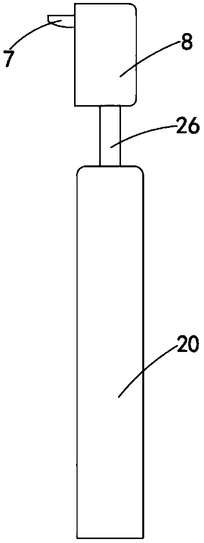
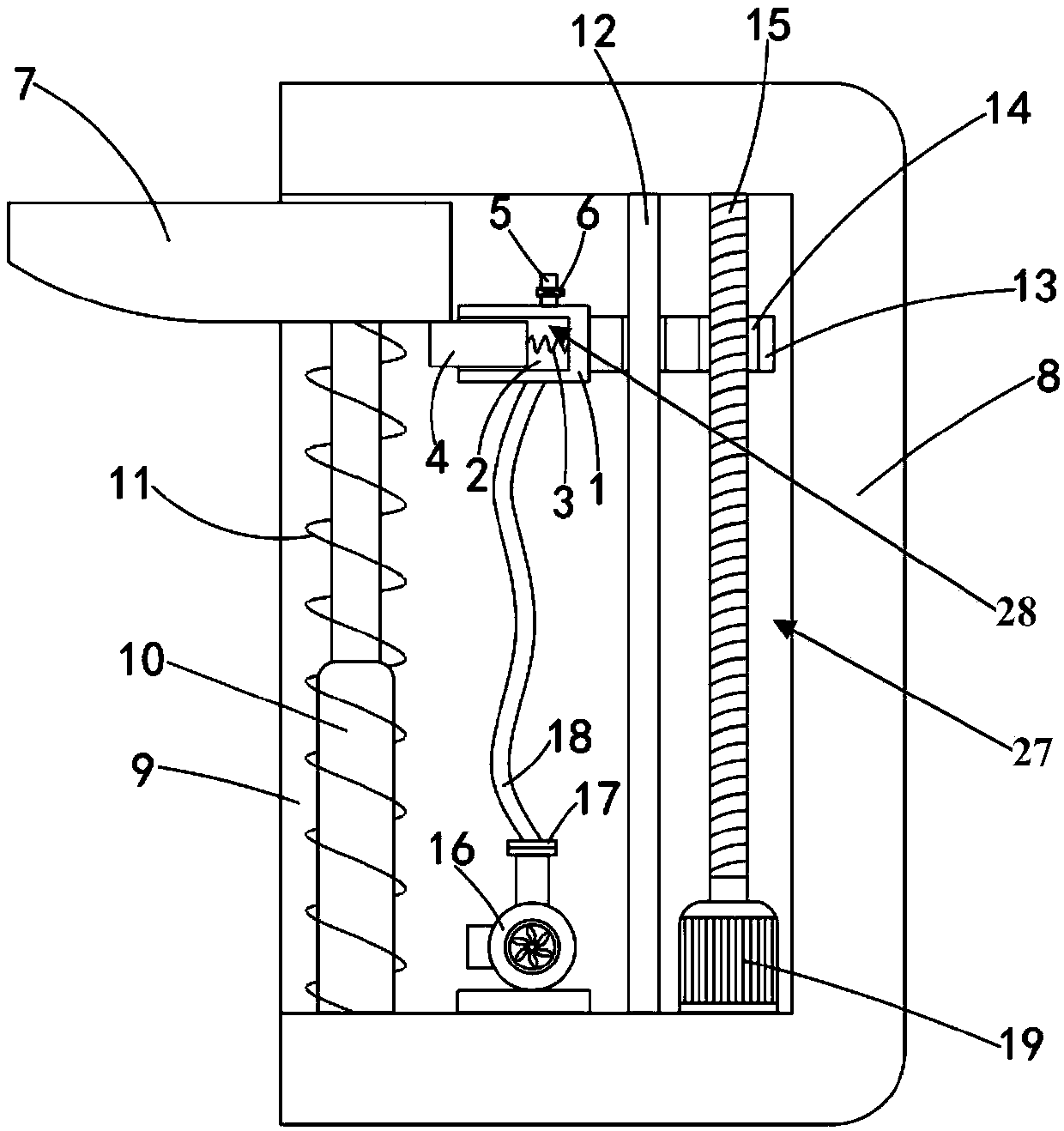
The invention discloses an auxiliary force augment hammer mechanism for a power system operating rod. The auxiliary force augment hammer mechanism is mounted on an operating rod and comprises a mounting block, a telescopic rod, a cutter, a connecting rod, a horizontal plate, a threaded rod, a servo motor and a stopping mechanism. A mounting groove is formed on the mounting block. The telescopic rod is vertically installed on one side in the mounting slot. The cutter is fixedly mounted on the upper end of the telescopic rod. The telescopic rod is sleeved with a first tension spring. The lower end of the first tension spring is fixed to the bottom of the mounting groove. The upper end of the first tension spring is fixed to the bottom of the cutter. The upper and lower ends of the connectingrod are fixedly connected to the top and the bottom of the mounting groove respectively. The connecting rod is sleeved with the horizontal plate. The horizontal plate is equipped with a screw hole ona side away from the cutter. The horizontal plate sleeves the upper end of the threaded rod through the screw hole. The stopping mechanism is arranged near the cutter. The servo motor is mounted on aside of the mounting groove. The lower end of the threaded rod is fixedly connected to the output end of the servo motor. The length of the operating rod can be adjusted to adapt to different alive circuits. The on-off of an isolating switch is realized by the auxiliary force augment hammer mechanism, the labor intensity of a worker is reduced, and the operation is simple and easy.

Description

technical field [0001] The invention relates to the field of live operating tools in electric power systems, in particular to an auxiliary force hammer mechanism for operating rods in electric power systems. Background technique [0002] The insulating operating rod is an insulating tool specially used for power systems, and can be used for live work, live maintenance and live maintenance work equipment. In the power system, the isolating switch is mainly used to reliably isolate the part that needs to be powered off from the live part in the high-voltage power distribution device, so as to ensure the safety of maintenance work. The isolating switch can also be used to switch certain circuits to change the operation mode of the system. Usually, the opening and closing of the isolating switch is completed through the hook at the front end of the operating rod. [0003] However, in the actual operation of the current electric operating lever, it is often difficult to pull and...

Claims


Application Information

Patent Timeline
Patent Type & Authority Applications(China)
IPC IPC(8): H01H3/02H01H31/00
CPCH01H3/02H01H31/006
Inventor 孟洁吕国远单晓怡
Owner STATE GRID TIANJIN ELECTRIC POWER
Learn More