Unwinding device for residual yarn on surfaces of ring bobbins and control method thereof
A control method and spinning bobbin technology, applied in the textile field, can solve problems such as low success rate of residual yarn unwinding, high labor intensity of residual yarn unwinding, low labor intensity and other problems, so as to improve unwinding effect and unwinding Winding reliability, low unwinding labor intensity, good unwinding effect
- Summary
- Abstract
- Description
- Claims
- Application Information
AI Technical Summary
Problems solved by technology
Method used
Image


Examples
Embodiment 1
[0055] see Figure 1 to Figure 9 , a device for unwinding residual yarn on the surface of a spun bobbin, comprising an annular guide rail 1 and a transport trolley 2 slidably connected thereon, a timing belt 3 is arranged on the inner side of the annular guide rail 1, and the synchronous belt 3 is connected with the transport trolley 2, the The conveying trolley 2 is horizontally provided with a plurality of bushings 21 for the spun yarn tube 4, the conveying trolley 2 is provided with a connecting bracket 22, and the connecting bracket 22 is provided with a plurality of bearing housings 23, and the bearing housing 23 passes through the bearing 24 A connecting rod 25 is sleeved, one end of the connecting rod 25 is connected with the casing 21, and the other end of the connecting rod 25 is sleeved with a pulley 26, and the conveying trolley 2 is provided with a rotating motor 27, and the output end of the rotating motor 27 passes through a belt 28 It is connected to the belt pu...
Embodiment 2
[0058] Basic content is the same as embodiment 1, the difference is:
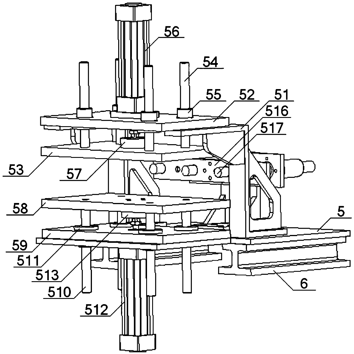
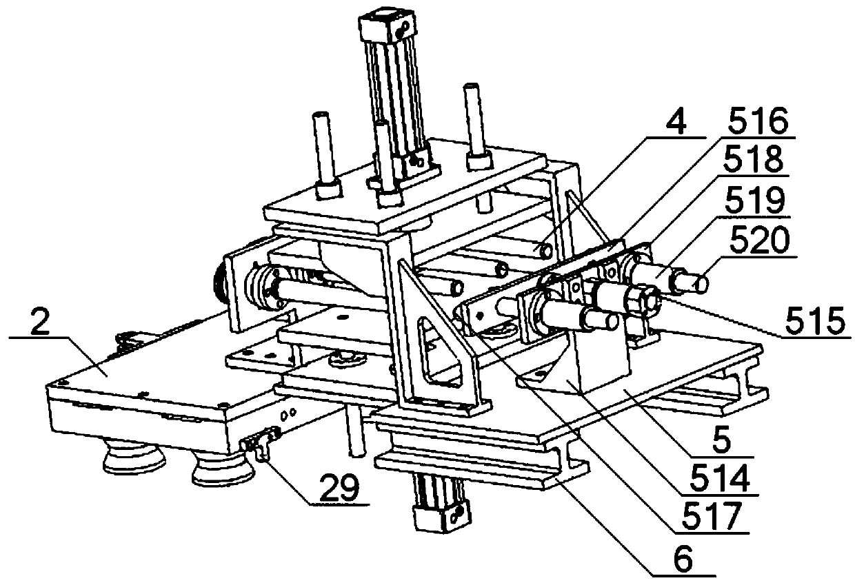
[0059] see figure 2 , image 3 , Figure 5, No. 2 bracket 514 is provided on the installation bottom plate 5, and No. 3 cylinder 515 connected with No. 1 installation board 516 is provided on No. 2 bracket 514, and a plurality of top cones 517 are arranged on No. 1 installation board 516; The No. 2 mounting plate 518 is set on the No. 2 bracket 514, the No. 2 mounting plate 518 is parallel to the No. 1 mounting plate 516, the No. 3 linear bearing 519 is arranged on the No. 2 mounting plate 518, and the No. 3 linear bearing 519 is equipped with a No. 3 linear bearing. Guide rod 520, No. 3 guide rod 520 is connected with No. 1 mounting plate 516, and described No. 3 cylinder 515 is arranged on No. 2 mounting plate 518, and the output end of No. 3 cylinder 515 passes through No. 2 mounting plate 518 and connects with No. 1 mounting plate 518. No. mounting plate 516 is connected; the spun bobbin 4 is a roun...
Embodiment 3
[0062] Basic content is the same as embodiment 1, the difference is:
[0063] see figure 1 , Figure 9 , the No. 1 bracket 51 is a Z-shaped structure, and the No. 1 bracket 51 includes a No. 1 horizontal plate 521, a No. 2 horizontal plate 522, and a vertical plate 523. The No. 1 horizontal plate 521 is connected with the No. 1 fixed plate 52, The end of the No. 1 horizontal plate 521 is connected with one end of the vertical plate 523, the other end of the vertical plate 523 is connected with the end of the No. 2 horizontal plate 522, and the No. 2 horizontal plate 522 is connected with the installation base plate 5; A No. 1 support plate 524 is arranged between the No. horizontal plate 521 and the vertical plate 523, and a No. 2 support plate 525 is arranged between the No. 2 horizontal plate 522 and the vertical plate 523. The No. 1 support plate 524 and the No. 2 support plate 525 are provided with lightening holes 526 .
PUM
 Abstract
Description
Claims
Application Information
 - R&D
- Intellectual Property
- Life Sciences
- Materials
- Tech Scout
- Unparalleled Data Quality
- Higher Quality Content
- 60% Fewer Hallucinations
Browse by: Latest US Patents, China's latest patents, Technical Efficacy Thesaurus, Application Domain, Technology Topic, Popular Technical Reports.
© 2025 PatSnap. All rights reserved.Legal|Privacy policy|Modern Slavery Act Transparency Statement|Sitemap|About US| Contact US: help@patsnap.com