Image acquisition equipment

An image acquisition and equipment technology, applied in mechanical equipment, supporting machines, machines/brackets, etc., can solve problems such as inability to accurately detect industrial testing equipment

Pending Publication Date: 2019-03-22
WATRIX TECH CORP LTD +1
View PDF7 Cites 0 Cited by
  • Summary
  • Abstract
  • Description
  • Claims
  • Application Information

AI Technical Summary

Problems solved by technology

[0004] The purpose of the present invention is to provide an image acquisition device to solve the technical problem that the existing industrial detection equipment cannot accurately detect

Method used


Image

  • Image acquisition equipment
  • Image acquisition equipment
  • Image acquisition equipment

Examples


Embodiment Construction

[0055] The technical solutions of the present invention will be clearly and completely described below in conjunction with the accompanying drawings. Apparently, the described embodiments are some of the embodiments of the present invention, but not all of them. Based on the embodiments of the present invention, all other embodiments obtained by persons of ordinary skill in the art without making creative efforts belong to the protection scope of the present invention.

[0056]In the description of the present invention, it should be noted that the terms "center", "upper", "lower", "left", "right", "vertical", "horizontal", "inner", "outer" etc. The indicated orientation or positional relationship is based on the orientation or positional relationship shown in the drawings, and is only for the convenience of describing the present invention and simplifying the description, rather than indicating or implying that the referred device or element must have a specific orientation, o...


PUM


Abstract

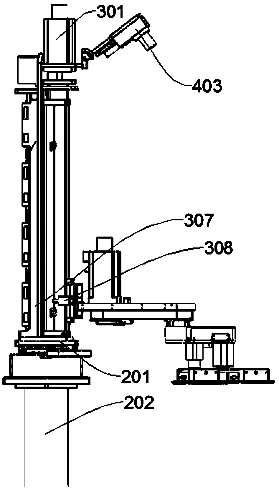
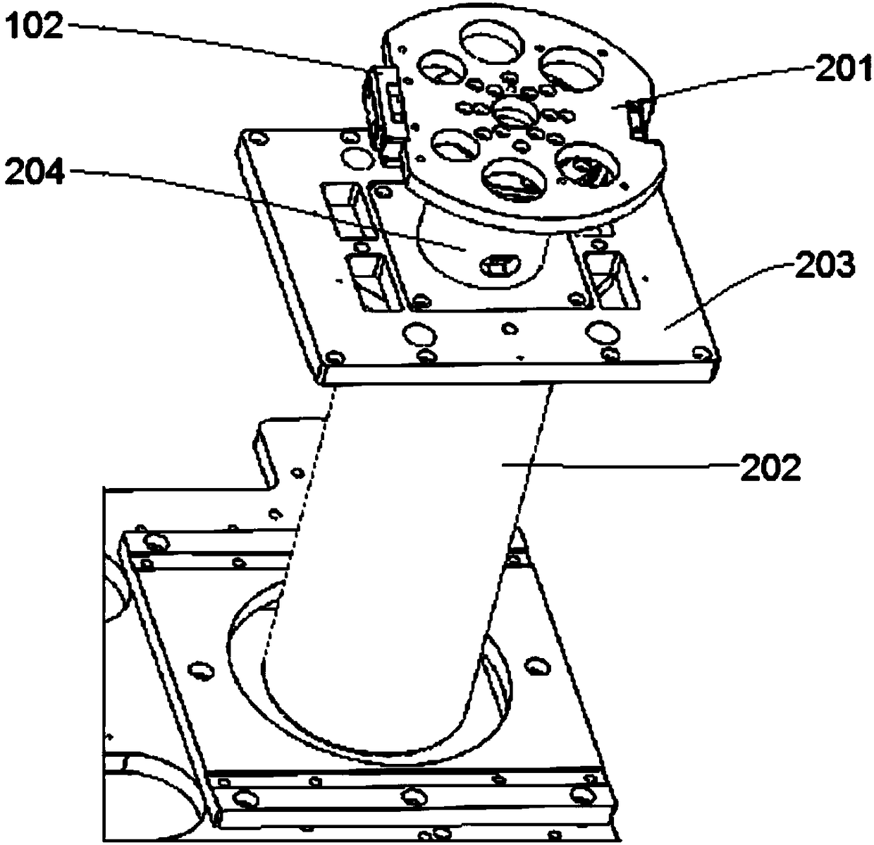
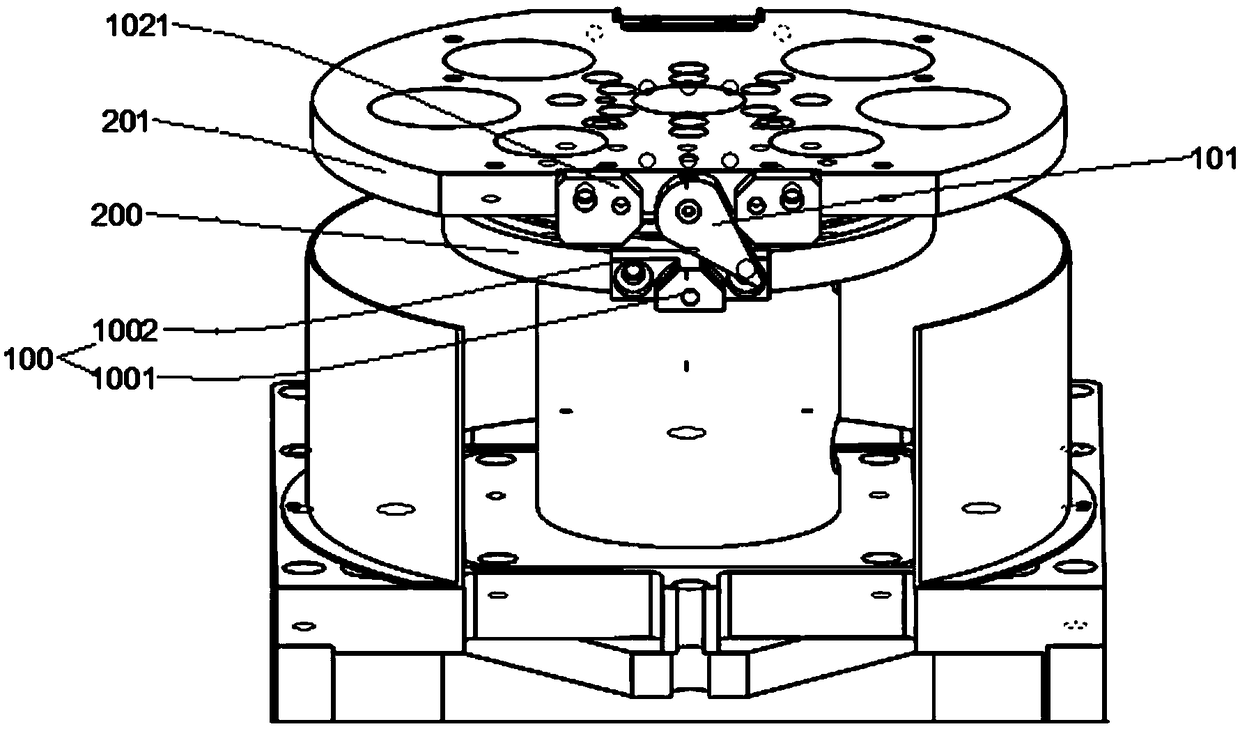
The invention provides image acquisition equipment, and relates to the field of industrial detection equipment. The image acquisition equipment comprises a lifting device, a rotating device and an image acquisition device; the rotating device comprises a driving mechanism, a mounting base and a rotating limit mechanism; the fixed part of the driving mechanism is fixedly connected with the mountingbase; the output end of the driving mechanism is fixedly connected with a rotating part, and an installation part is driven by the driving mechanism to rotate and move; the mounting base is providedwith a fixing part; the rotating limit mechanism is arranged between the rotating part and the fixing part, and used for limiting the rotating angle of the rotating part; the lifting device is installed on the rotating part; the image acquisition device comprises a connecting structure and an image acquisition mechanism; the image acquisition mechanism is installed on the top of the lifting devicethrough the connecting structure; and the image acquisition mechanism can be swung through the connecting structure. According to the image acquisition equipment, the problem that accurate detectionof existing industrial detection equipment can not be achieved is solved.

Description

technical field [0001] The invention relates to the technical field of industrial testing equipment, in particular to an image acquisition equipment. Background technique [0002] In the field of AGV trolleys for industrial inspection, the limit mechanism of some rotating shafts generally adopts a dead stop point or a flat groove mechanism. The dead stop point will affect the rotation, resulting in a rotation angle of less than 360°. Moreover, the planar groove mechanism has movement limitations, and is not suitable for some special occasions. If it is used forcibly, the manufacturing cost will be increased. Therefore, its video acquisition device cannot sometimes reach a suitable angle and cannot detect accurately. Moreover, its video acquisition device is generally fixed and cannot move, so the monitoring accuracy and range are relatively low. [0003] Based on this, the present invention provides an image acquisition device to solve the above technical problems. Conten...

Claims


Application Information

Patent Timeline
Patent Type & Authority Applications(China)
IPC IPC(8): F16M11/04F16M11/06F16M11/18F16M11/42
CPCF16M11/046F16M11/06F16M11/18F16M11/425
Inventor 黄永祯王凯曹春水
Owner WATRIX TECH CORP LTD
Why Eureka
Try Eureka