
Magnetic circuit split type v-type parallel combined magnetic pole adjustable flux motor

A technology combining magnetic pole and magnetic flux motor, applied in the direction of magnetic circuit shape/style/structure, magnetic circuit, magnetic circuit rotating parts, etc., can solve the problem of reducing the capacity of the motor drive controller, expanding the load magnetization multiple, reducing the motor pulse size and other issues, to achieve the effect of good air gap magnetic density, weakening the demagnetization effect, and reducing the amplitude of the pulse current

Active Publication Date: 2021-03-02
HARBIN INST OF TECH
View PDF3 Cites 0 Cited by
  • Summary
  • Abstract
  • Description
  • Claims
  • Application Information

AI Technical Summary

Problems solved by technology

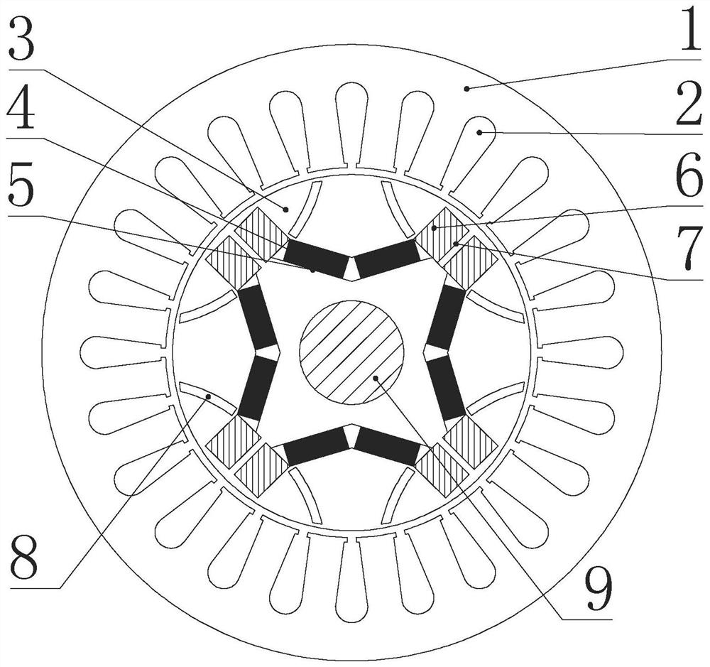
[0003] The purpose of the present invention is to solve the problem of inhibiting the demagnetization effect of high coercive force permanent magnets in motors with high coercive force and low coercive force permanent magnet combined magnetic pole structures, and to provide a magnetic circuit split type V-type parallel combined magnetic poles Adjustable flux motor, because the motor places an arc-shaped magnetic barrier above the intersection of the two permanent magnets under the same pole, the demagnetization effect of the high-coercivity permanent magnet of the motor on the low-coercivity permanent magnet is weakened, The size of the magnetizing current pulse required by the motor is reduced, the capacity of the drive controller required by the motor is reduced, and the load magnetization multiple is expanded; at the same time, the arc-shaped magnetic barrier redistributes the magnetic flux generated by the permanent magnet poles, improving the Fundamental wave amplitude and sine degree of motor no-load air gap flux density

Method used


Image

  • Magnetic circuit split type v-type parallel combined magnetic pole adjustable flux motor
  • Magnetic circuit split type v-type parallel combined magnetic pole adjustable flux motor

Examples


Embodiment Construction

[0017] The implementation of the present invention will be described in detail below in conjunction with the accompanying drawings and examples, so as to fully understand and implement the process of how to apply technical means to solve technical problems and achieve technical effects in the present invention. It should be noted that, as long as there is no conflict, each embodiment and each feature in each embodiment of the present invention can be combined with each other, and the formed technical solutions are all within the protection scope of the present invention.

[0018] The magnetic circuit split type V-type parallel combined magnetic pole adjustable flux motor includes a stator core 1, a stator winding 2, a rotor core 3 and a rotating shaft 9; the rotor core 3 is fixed on the rotating shaft 9 and is located inside the stator core 1, and the stator winding 2 set on the stator core 1;

[0019] It also includes a high-coercivity permanent magnet 4, a high-coercivity pe...


PUM

PropertyMeasurementUnit
coercivityaaaaaaaaaa

Abstract

The invention discloses a V-shaped parallel combined magnetic-pole adjustable magnetic flux motor of a magnetic circuit segmentation type, and belongs to the field of permanent magnet motors. The invention aims at solving a problem that a motor which employs a combined magnetic-pole structure of high-coercivity and low-coercivity permanent magnets inhibits the demagnetizing action of the high-coercivity permanent magnet. According to the technical scheme of the invention, each pole of a rotor core is provided with a V-shaped high-coercivity permanent magnet slot, and is symmetrically providedwith a pair of rectangular and axially-through low-coercivity permanent magnet slots. Two mouths of the V-shaped high-coercivity permanent magnet slot are respectively communicated with the rectangular and axially-through low-coercivity permanent magnet slots, and two adjacent low-coercivity permanent magnet slots under different magnetic poles are parallel. The interior of the high-coercivity permanent magnet slot is provided with the high-coercivity permanent magnet, and the interior of each V-shaped low-coercivity permanent magnet slot is provided with one low-coercivity permanent magnet. Apair of arc-shaped magnetic barriers are disposed under the same magnetic pole, and the magnetic barriers are arranged at the intersections of two types of permanent magnets. Two adjacent magnetic barriers under different magnetic poles are located in the same internal recessed arc.

Description

technical field [0001] The invention belongs to the field of permanent magnet motors and relates to wide speed regulation technology of permanent magnet motors. Background technique [0002] Permanent magnet synchronous motor has become a common drive motor for new energy vehicles due to its advantages of high power density and high efficiency. However, this type of motor has disadvantages such as difficulty in adjusting the permanent magnet magnetic field and low efficiency when the field is weakened. In response to the above problems, scholars have proposed an adjustable flux motor with an adjustable permanent magnet field. This motor can change the magnetization state of the permanent magnet by applying d-axis charging and demagnetizing current pulses, so as to expand the motor speed regulation range. the goal of. Compared with an adjustable flux motor using only one low-coercivity permanent magnet, a motor with a combined pole structure of high-coercivity and low-coerci...

Claims


Application Information

Patent Timeline
Patent Type & Authority Patents(China)
IPC IPC(8): H02K1/27H02K21/02
CPCH02K1/2766H02K21/025
Inventor 王明峤佟诚德郑萍程路明乔光远刘法亮
Owner HARBIN INST OF TECH
Learn More