Display device and backlight driving method

A display device and backlight driving technology, applied in static indicators, instruments, etc., can solve the problem that the backlight module cannot be quickly turned on

Active Publication Date: 2019-03-19
AU OPTRONICS CORP
View PDF7 Cites 0 Cited by
  • Summary
  • Abstract
  • Description
  • Claims
  • Application Information

AI Technical Summary

Problems solved by technology

Especially in the game scene or when testing the display panel, it may happen that the backlight module needs to be turned on quickly. However, the previous backlight driving technology cannot turn on the backlight module quickly, so the desired effect cannot be achieved

Method used


Image

  • Display device and backlight driving method
  • Display device and backlight driving method
  • Display device and backlight driving method

Examples


Embodiment Construction

[0027] Below in conjunction with accompanying drawing, structural principle and working principle of the present invention are specifically described:

[0028] Embodiments of the present invention will be described below in conjunction with related figures. In the drawings, the same reference numerals represent the same or similar elements or method flows.

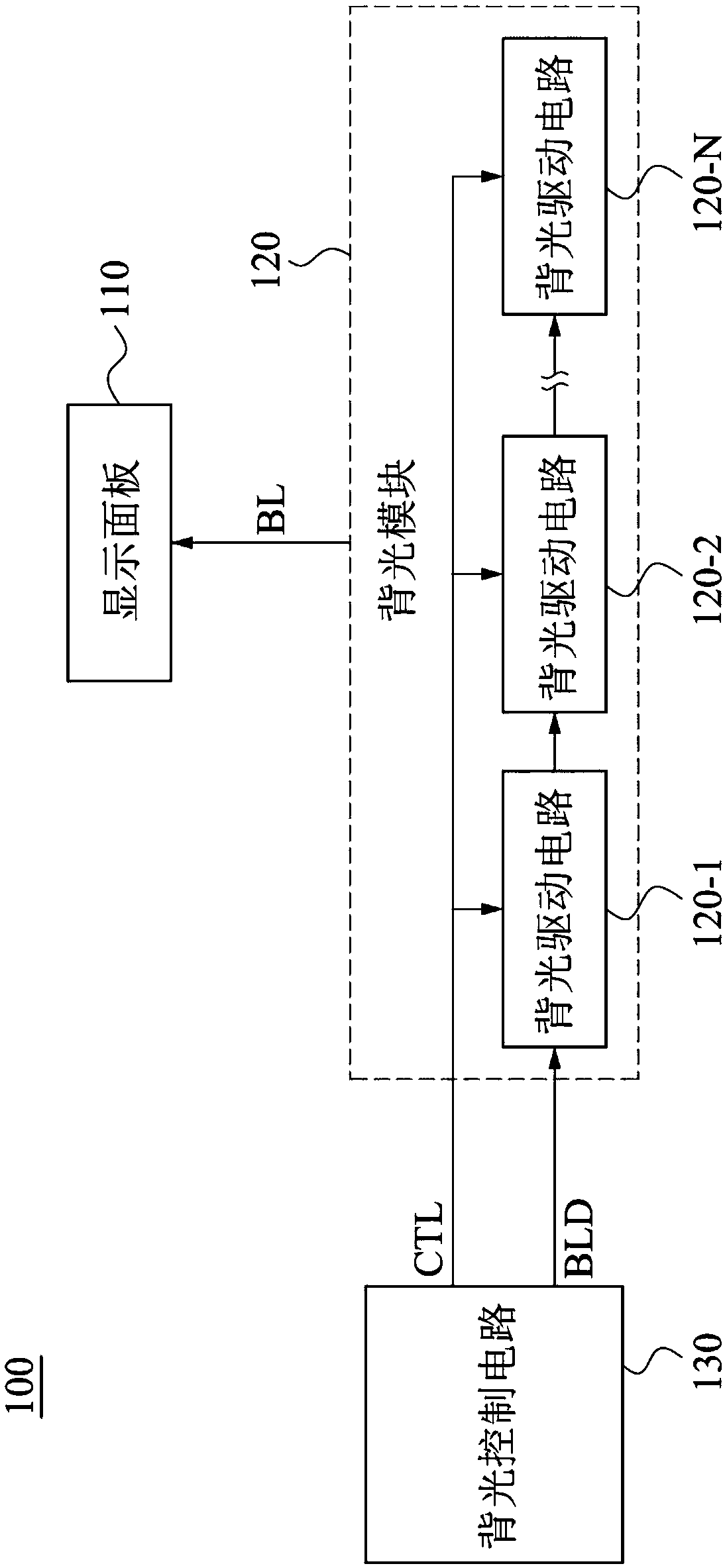
[0029] see figure 1 . figure 1 is a schematic diagram of a display device 100 according to an embodiment of the present invention. Such as figure 1 As shown, the display device 100 includes a display panel 110 , a backlight module 120 and a backlight control circuit 130 , and the backlight module 120 includes a plurality of backlight driving circuits 120 - 1 - 120 -N. In one embodiment, the backlight module 120 is generally disposed on a direct-lit backlight module or an edge-lit backlight module relative to the lower side (not shown in the figure) of the display panel 110. module. The backlight module 120 is electri...


PUM


Abstract

A display device includes a display panel, a backlight module, and a backlight control circuit. The backlight module is electrically connected to the display panel to provide a backlight for the display panel. The backlight module further includes a plurality of backlight driving circuits. The backlight control circuit is electrically connected to the backlight module, and the backlight control circuit is configured to control the backlight module and operate in one of a first display mode and a second display mode.

Description

technical field [0001] The invention relates to a display device and a backlight driving method, in particular to a display device and a backlight driving method for rapidly switching the brightness of the backlight. Background technique [0002] Today's display panels mostly use passive light-emitting technology, which uses the action of the liquid crystal to block or open the light of the backlight module to display the picture. Since the transition of the liquid crystal takes time, the response speed of the liquid crystal and the turn-on time of the backlight module are different in the display panel. It has always been a problem that needs to be solved in the technical field. Especially in the game scene or when testing the display panel, it may happen that the backlight module needs to be turned on quickly. However, the conventional backlight driving technology cannot turn on the backlight module quickly, so the desired effect cannot be achieved. Contents of the inven...

Claims


Application Information

Patent Timeline
Patent Type & Authority Applications(China)
IPC IPC(8): G09G3/34G09G3/36
CPCG09G3/3406G09G3/36G09G2320/062
Inventor 陈世轩熊国佑
Owner AU OPTRONICS CORP
Why Eureka
Try Eureka