
Optical communication module

An optical communication module and optical fiber technology, applied in the field of optical communication modules, can solve the problems affecting the performance of the optical communication module and the limitation of light detection components, and achieve the effect of increasing the flexibility of setting and improving the performance.

Active Publication Date: 2021-01-05
ORANGETEK CORP
View PDF1 Cites 0 Cited by
  • Summary
  • Abstract
  • Description
  • Claims
  • Application Information

AI Technical Summary

Problems solved by technology

[0004] The purpose of the present invention is to provide an optical communication module, which can improve the performance of the optical communication module due to excessive assembly errors in the actual use of the aforementioned existing optical communication modules, and can improve the performance of the circuit board. on set photodetection elements are limited by the lack of

Method used


Image

  • Optical communication module
  • Optical communication module
  • Optical communication module

Examples


Embodiment Construction

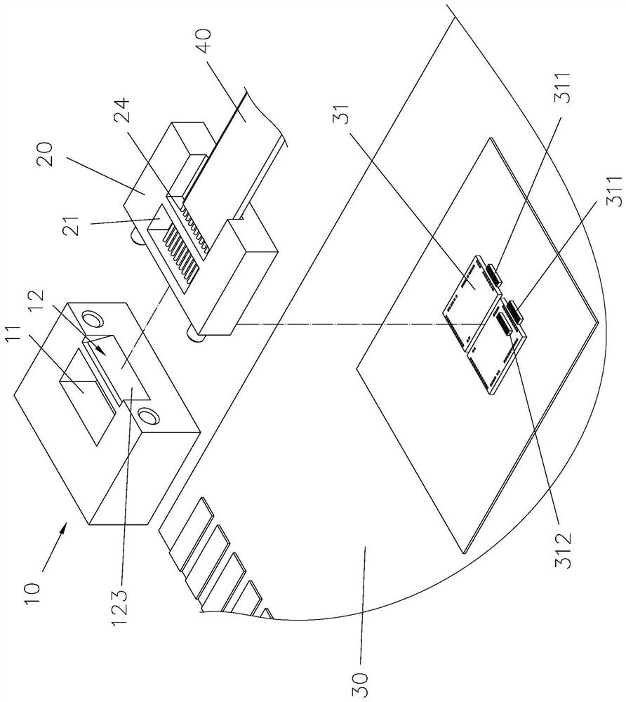
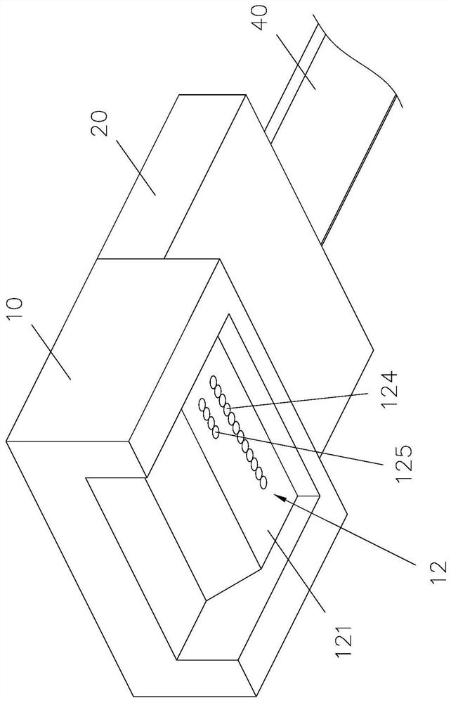
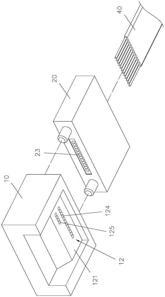
[0026] Please refer to Figure 1 to Figure 4 As shown, the optical communication module of the present invention includes a light-transmitting lens element 10 , a light-transmitting fiber fixing member 20 , a circuit board 30 and at least one optical fiber 40 .

[0027] Please also see Figure 5 As shown, one side of the lens element 10 is concave with a groove 100, and the lens element 10 forms a lens structure 12 on one side of the groove 100, and one side of the lens structure 12 forms a top surface 11, and the lens structure 12 is away from One side of the top surface 11 forms a light-incident surface 121, and the light-incident surface 121 is provided with a plurality of collimating lenses 124 and a plurality of light-receiving lenses 125 on a side different from the top surface 11, and a side surface of the lens structure 12 forms a reflecting slope 122 , the reflective slope 122 is formed with a main reflective surface 1221 and a secondary reflective surface 1222, the ...


PUM


Abstract

The invention relates to an optical communication module which comprises a light-permeable lens component, a light-permeable fiber fixed part, at least one fiber and a circuit board. The lens component forms a lens structure body, an opening and a light input surface are formed in the top and bottoms sides of the lens structure body respectively, the light input surface is provided with at least one collimating lens, an inclined relation plane and a light output surface are formed in the opposite sides of the lens structure body respectively, the collimating lens is positioned within the orthographic projection scope in the vertical visual angle of the inclined reflection plane, the fiber fixed part is arranged in the side towards the light output surface of the lens component, a dispensing groove is formed in one side of the fiber fixed part, the fiber fixed part is provided with at least one focusing lens, the focusing lens corresponds to the orthographic projection scope in the horizontal visual angle of the light output surface, the fiber penetrates the dispensing groove of the lens component, a fixing glue is filled into the dispensing groove of the lens component, and thus, the fiber is fixed to the lens component, and one end of the fiber is aligned to the position of the focusing lens.

Description

technical field [0001] The invention belongs to the technical field of optical communication modules, in particular to an optical communication module that can effectively improve assembly tolerance tolerance. Background technique [0002] Commonly known optical communication modules, such as China's approved patent case No. 103885140 "optical components and assembly methods for passive coupling of chip arrays and parallel optical fibers", please refer to Figure 7 As shown, it is provided with a photoelectric chip array 500 on a chip carrier 50, and a lens body 51 and a fixing seat 52 are provided on the chip carrier 50, and a reflective surface 510 is provided in the lens body 51, and the lens body 51 is relatively reflective The vertical surface of the surface 510 forms a first lens array surface 511, the lens body 51 forms a second lens array surface 512 relative to the horizontal surface of the reflective surface 510, and the fixing seat 52 is provided with a multi-layer...

Claims


Application Information

Patent Timeline
Patent Type & Authority Patents(China)
IPC IPC(8): G02B6/42
CPCG02B6/4204G02B6/4214G02B6/4239G02B6/4243
Inventor 陈俊傑郭朝辉叶俊毅卢冠甫
Owner ORANGETEK CORP
Learn More