
Battery throwing method and device for prolonging airtime of electric multi-rotor, and unmanned aerial vehicle

A throwing device and multi-rotor technology, which is applied to power devices, launching devices, and unmanned aircraft on aircraft, can solve problems such as limiting the application of multi-rotor UAVs, reducing flight time, and failing to achieve rapid technological breakthroughs.

Pending Publication Date: 2019-03-01
智灵飞(北京)科技有限公司
View PDF6 Cites 4 Cited by
  • Summary
  • Abstract
  • Description
  • Claims
  • Application Information

AI Technical Summary

Problems solved by technology

Or use an oil machine, but this increases the mechanical transmission, which is not conducive to maintenance and repair
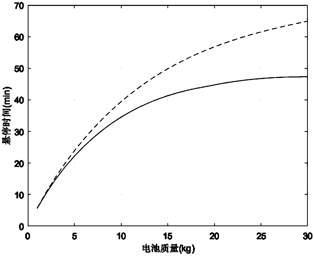
[0003] To sum up, the problems existing in the existing technology are: when the existing multi-rotor UAVs achieve long range, they can only carry smaller loads; carrying large loads can only reduce the flight time, which seriously limits the performance of multi-rotor drones. UAV application
However, the capacity-to-mass ratio of the battery and the efficiency of the power system cannot achieve rapid technological breakthroughs in a short period of time.

Method used


Image

  • Battery throwing method and device for prolonging airtime of electric multi-rotor, and unmanned aerial vehicle
  • Battery throwing method and device for prolonging airtime of electric multi-rotor, and unmanned aerial vehicle
  • Battery throwing method and device for prolonging airtime of electric multi-rotor, and unmanned aerial vehicle

Examples


Embodiment Construction

[0037] In order to make the objectives, technical solutions and advantages of the present invention clearer, the present invention will be further described in detail below in conjunction with embodiments. It should be understood that the specific embodiments described herein are only used to explain the present invention, but not to limit the present invention.

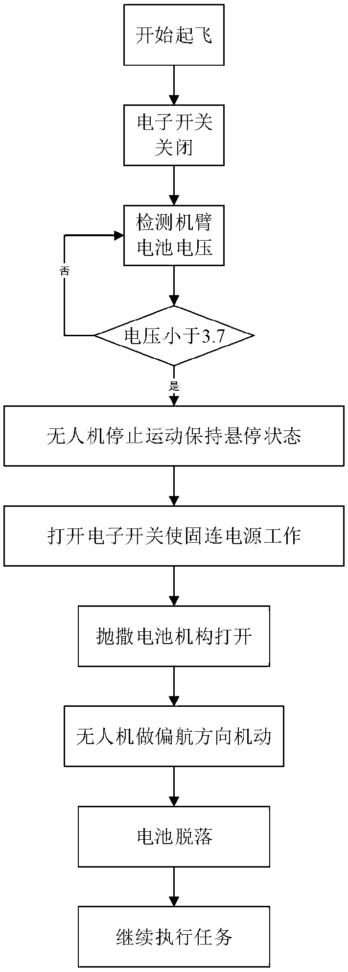
[0038] In view of the problem that the existing multi-rotor UAV can only carry a smaller load when it obtains a long flight; carrying a large load can only reduce the flight time, which seriously limits the application of the multi-rotor UAV; A battery throwing mechanism is added to the arm, and the drone quickly turns by yaw to throw away the battery. It can ensure that the battery on each arm can be dropped off, and the simultaneity of dropping off can be guaranteed, which is beneficial to maintaining the attitude of the electric multi-rotor.

[0039] The application principle of the present invention will be described...


PUM


Abstract

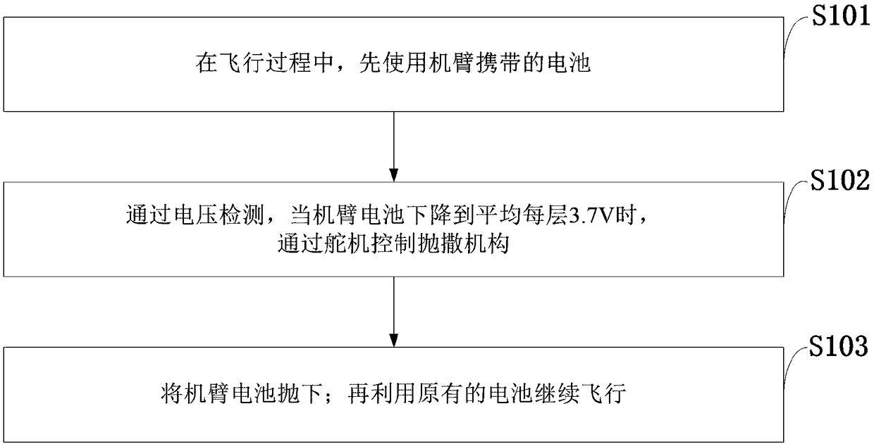
The invention belongs to the technical field of multi-rotor unmanned aerial vehicles, and discloses a battery throwing device and method for prolonging the airtime of an electric multi-rotor, and an unmanned aerial vehicle. The battery throwing method includes the steps that batteries carried on vehicle arms are firstly used during flight; through voltage detection, the batteries of the vehicle arms drop to an average of 3.7 V per layer, and a throwing mechanism is controlled through steering engines; the batteries of the vehicle arms are dropped; and a battery of a vehicle body is then used for continue flight. According to the battery throwing device and method for prolonging the airtime of the electric multi-rotor, and the unmanned aerial vehicle, in order to ensure that the batteries can be safely and synchronously separated from the vehicle arms of the electric unmanned aerial vehicle, the mechanical action needs to be done when the throwing mechanism is opened, the payload is interfered to prevent the batteries from falling, and the electric unmanned aerial vehicle throws the batteries through a hovering mode; after the throwing mechanism is opened, the yaw is rapidly rotatedat an angle by the unmanned aerial vehicle at the same time, and the batteries are thrown off; and it can be ensured that the batteries on the vehicle arms can fall off, the synchroneity of falling off can be ensured, and the attitude of the electric multi-rotor is maintained.

Description

Technical field [0001] The invention belongs to the technical field of multi-rotor unmanned aerial vehicles, and in particular relates to a battery throwing method and device for extending the flight time of an electric multi-rotor unmanned aerial vehicle. Background technique [0002] At present, the existing technology commonly used in the industry is as follows: Multi-rotor drones have been extensively studied in recent years. It is highly maneuverable, can hover at a fixed point, has a simple structure and is easy to operate, which has attracted continuous attention in various fields. It has applications in aerial photography, plant protection, surveying and mapping, power line inspections, short-distance transportation, police and military applications. With continuous breakthroughs in technology, multi-rotor drones are bound to undertake more and heavier tasks. For example, in a fire situation, carrying fire extinguishing bombs, provided that the round-trip time is met, i...

Claims


Application Information

Patent Timeline
IPC IPC(8): B64D1/02B64D27/24B64D31/00
CPCB64D1/02B64D27/24B64D31/00B64U50/19Y02T50/60
Inventor 丁久辉韩冬
Owner 智灵飞(北京)科技有限公司
Learn More