
Dental orthodontic device and method

A tooth and orthodontic technology, applied in the direction of brackets, arch wires, etc., can solve the problems that the orthodontic effect cannot reach the expected ideal, hinder the orthodontic movement of the teeth, and the orthodontic effect is not ideal, so as to achieve good orthodontic effect and The transmission of force is sufficient and the effect of sufficient transmission

Pending Publication Date: 2019-03-01
HAINAN UNIVERSITY
View PDF5 Cites 9 Cited by
  • Summary
  • Abstract
  • Description
  • Claims
  • Application Information

AI Technical Summary

Problems solved by technology

[0003] However, when self-ligating brackets and arch wires are used for orthodontic teeth, due to the self-locking characteristics of self-ligating brackets, there is a huge resistance in the gap between the arch wires and self-ligating brackets. Kusy and Whitley will The sliding resistance that may occur during orthodontic archwire treatment is divided into three parts: 1. Friction due to the contact between the orthodontic archwire and the bracket surface; 2. Binding, when the tooth is tilted or the orthodontic archwire When there is bending, the orthodontic archwire will have binding contact with the corner of the bracket, which prevents the orthodontic archwire from exerting the corrective force on the teeth; 3. When the orthodontic archwire contacts the corner of the bracket When permanent deformation occurs at the place, a gap will appear; when such a gap occurs, the tooth will stop moving until the gap is restored; making the effect of orthodontics unable to achieve the desired ideal
[0004] For the self-locking bracket orthodontic devices commonly used in the market at present, although the friction force of the orthodontic archwire is reduced, the binding between the orthodontic archwire and the bracket and the appearance of gaps still hinder the teeth. Orthodontic movement, making the orthodontic effect unsatisfactory

Method used


Image

  • Dental orthodontic device and method
  • Dental orthodontic device and method
  • Dental orthodontic device and method

Examples


Embodiment

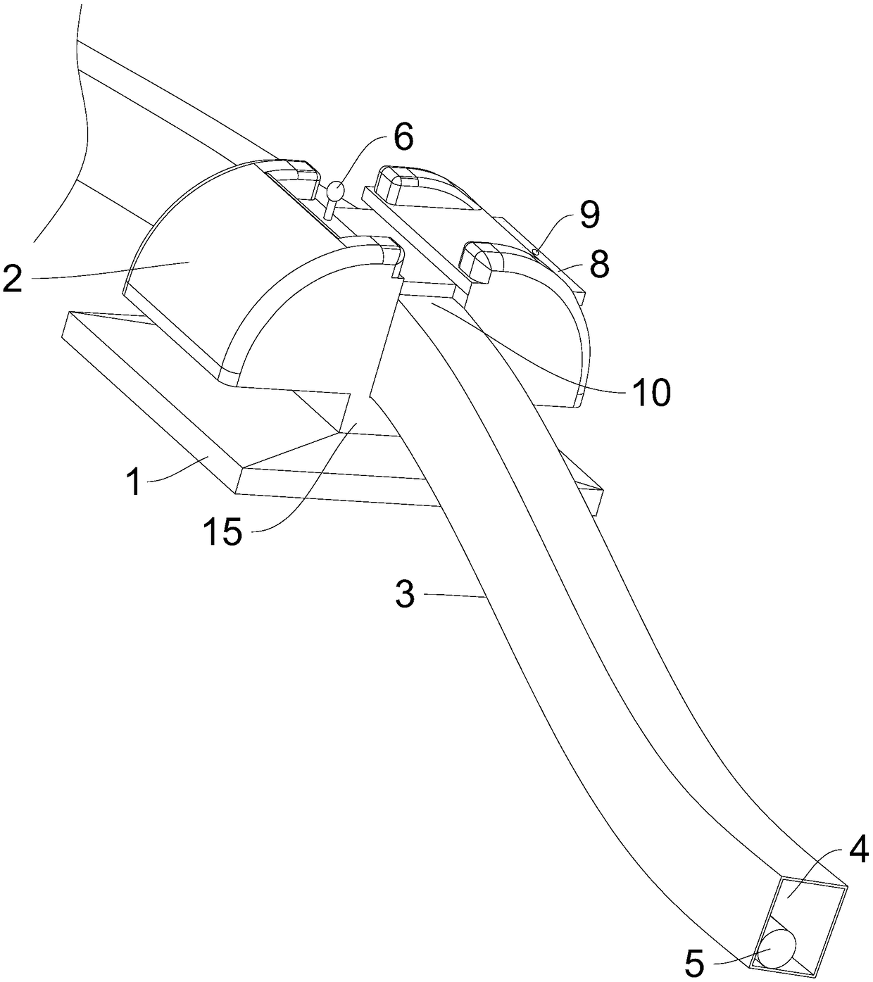
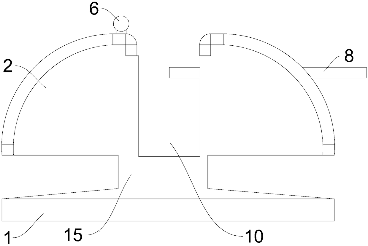
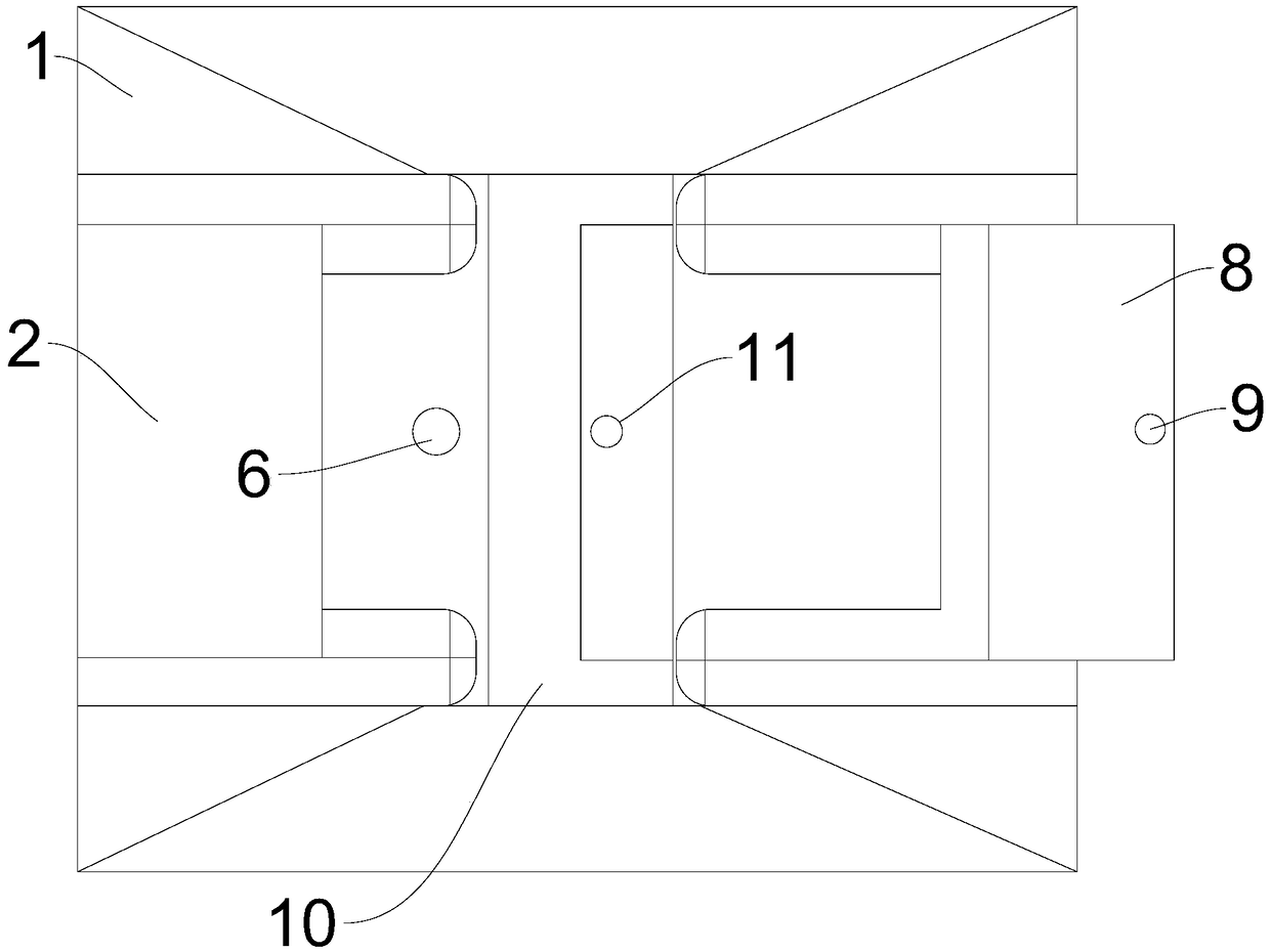
[0041] Such as figure 1 , figure 2 , image 3 and Figure 4 As shown, an orthodontic device includes a plurality of self-ligating brackets and an orthodontic archwire 5, the orthodontic archwire 5 is a commonly used standard orthodontic archwire 5, mainly made of nickel-titanium alloy metal , the cross section of the orthodontic archwire 5 is circular, with a diameter of 0.3mm-0.36mm, and the self-locking bracket is provided with an archwire groove 10, the archwire groove 10 is mainly used for placing the orthodontic archwire 5, and the orthodontic archwire 5. Form the correcting force on the teeth. The self-ligating bracket includes a bracket base plate 1, a connecting column 15 and a bracket body 2. The bracket base plate 1 is fixedly connected to one end of the connecting column 15. The bracket base plate 1 is mainly pasted on the surface of the teeth. , the bracket body 2 is fixedly connected with the other end of the connecting column 15. The bracket body 2 is semicir...


PUM

PropertyMeasurementUnit
Diameteraaaaaaaaaa
Wall thicknessaaaaaaaaaa

Abstract

The invention relates to a dental orthodontic device and method. The dental orthodontic device comprises a plurality of self-locking brackets and orthodontic arch wires, arch wire grooves are formed in the self-locking brackets, arc-shaped fixing arch wires with the same shape as teeth before orthodontics are placed in the arch wire grooves, inner cavities penetrating along the arc lines of the fixing arch wires and used for storing the orthodontic arch wires are formed in the fixing arch wires, and the orthodontic arch wires are placed in the inner cavities and bonded with the inner walls ofthe inner cavities. By arranging the orthodontic arch wires in the fixing arch wires, the orthodontic arch wires do not make direct contact with the self-locking brackets and do not generate resistance at bound notches between the orthodontic arch wires and the self-locking brackets, the orthodontic effects on the teeth is better, the original force applying faces between the arch wires and the brackets are enlarged, thus orthodontic force is transmitted more sufficiently, and the orthodontic treatment tooth moving efficiency is improved.

Description

technical field [0001] The invention relates to the technical field of orthodontics, in particular to a device and method for orthodontics. Background technique [0002] For the vast majority of fixed orthodontic treatment, orthodontic tooth movement mainly relies on the elastic deformation of the arch wire to reserve the force to move the tooth. . For many years, this kind of connection was mainly fixed by ligation, but now most of them use self-ligating brackets to replace the original brackets. Self-ligating brackets use lock caps instead of ligature wires or ligature rings to fix the archwires, which not only greatly It greatly reduces the chairside operation time, and at the same time greatly reduces the friction during the correction process, bringing more advantages to clinical orthodontics than traditional brackets, so it has been favored by the majority of orthodontists. increasingly widespread in clinical applications. [0003] However, when self-ligating bracke...

Claims


Application Information

Patent Timeline
IPC IPC(8): A61C7/34
CPCA61C7/34
Inventor 蔡永清
Owner HAINAN UNIVERSITY
Learn More