
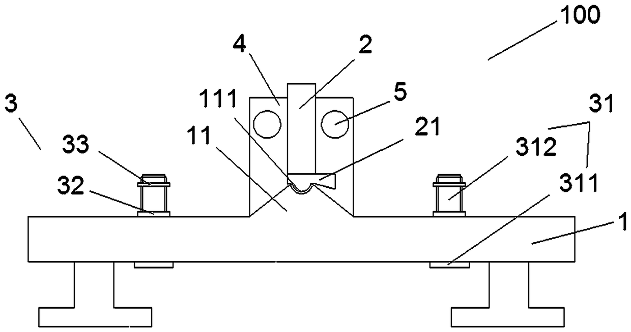
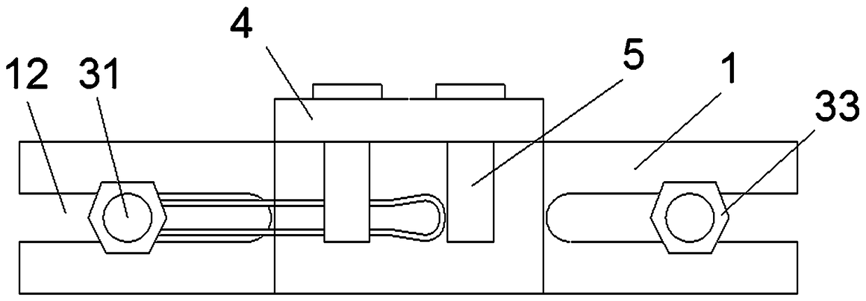
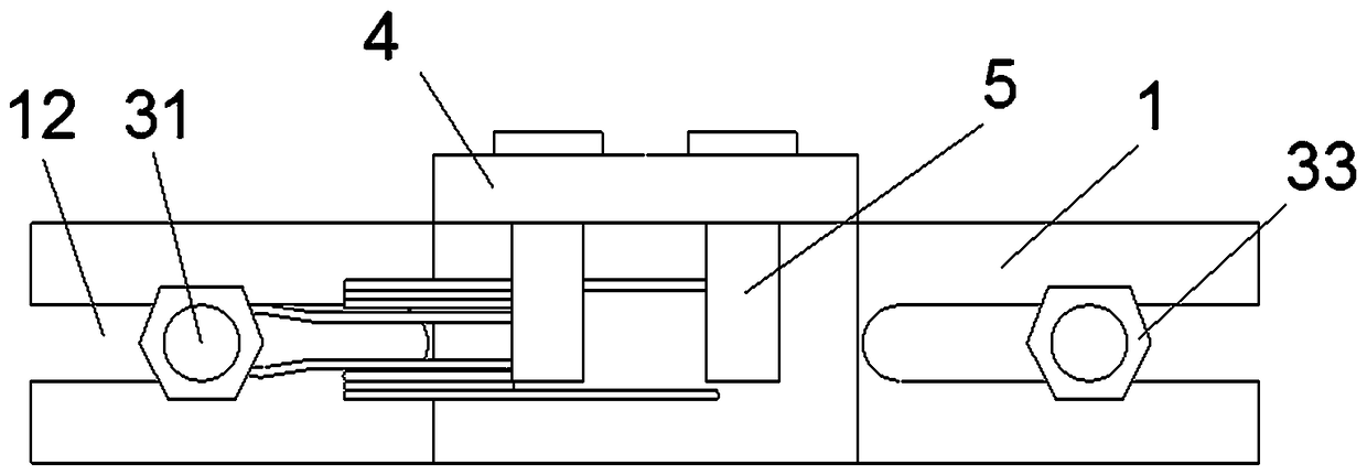
Stamping tool for semi-arc parts on torsional arms of middle and two ends of reset torsional spring

A stamping tool and semi-circular arc technology, which is applied in the field of torsion spring manufacturing, can solve the problems of inconsistency in the size of the torsion arm relative to the position, and the reduction of torque accuracy.

Active Publication Date: 2019-02-26
CHONGQING WANGJIANG IND
View PDF7 Cites 0 Cited by
  • Summary
  • Abstract
  • Description
  • Claims
  • Application Information

AI Technical Summary

Problems solved by technology

[0004] The object of the present invention is to provide a stamping tool for the semicircle arc part on the middle part of the compound torsion spring and the torsion arms at both ends, aiming at solving the problem of using the semicircle arc part in the middle part of the compound torsion spring and the torsion arms at both ends. Pliers or clamps are made by hand, which is easy to cause inconsistencies in the size and shape of the torsion arm and the relative position of the spring coil, and the accuracy of the torque is reduced.

Method used


Image

  • Stamping tool for semi-arc parts on torsional arms of middle and two ends of reset torsional spring
  • Stamping tool for semi-arc parts on torsional arms of middle and two ends of reset torsional spring
  • Stamping tool for semi-arc parts on torsional arms of middle and two ends of reset torsional spring

Examples


Embodiment Construction

[0017] Embodiments of the present invention are described in detail below, examples of which are shown in the drawings, wherein the same or similar reference numerals designate the same or similar elements or elements having the same or similar functions throughout. The embodiments described below by referring to the figures are exemplary and are intended to explain the present invention and should not be construed as limiting the present invention.

[0018] In describing the present invention, it is to be understood that the terms "upper", "lower", "front", "rear", "left", "right", "vertical", "horizontal" etc. indicate an orientation or The positional relationship is based on the orientation or positional relationship shown in the drawings, which is only for the convenience of describing the present invention and simplifying the description, rather than indicating or implying that the referred device or element must have a specific orientation, be constructed and operated in ...


PUM


Abstract

The invention discloses a stamping tool for semi-arc parts on torsional arms of the middle and two ends of a reset torsional spring. The stamping tool for the semi-arc parts on the torsional arms of the middle and two ends of the reset torsional spring comprises a concave die and a convex die, the concave die is provided with a protrusion part, and the protrusion part is fixedly connected with theconcave die, located in the center of the end face of the concave die, and provided with a groove; the groove is located in the side away from the concave die, the convex die is located above the concave die and provided a protrusion, the protrusion and the convex die are integrally formed, and the protrusion is located at the side close to the concave die and matched with the groove. One die stamps different positions of the torsional spring into the semi-arc parts with the same shape, position and size, the situation that the size and shape of the torsional arms are inconsistent with the size of those of a spring ring is avoided, and the torque precision is improved.

Description

technical field [0001] The invention relates to the technical field of torsion spring manufacturing, in particular to a stamping tool for the middle part of a compound torsion spring and the semicircle arc part of the torsion arms at both ends. Background technique [0002] Torsion springs can store and release angular energy or statically hold a device by rotating a moment arm about the central axis of the spring body. The ends of a torsion spring are fixed to other components, and when the other components are rotated about the center of the spring, the spring pulls them back to their original position, creating a torque or rotational force. [0003] The existing compound torsion spring middle part and semi-circular parts on the torsion arms at both ends are made by using a simple shape mold to cover the torsion arm ring, and using a vise or clamp to complete the shape and size of the production, handmade, shape and size It is difficult to control, and it is easy to cause...

Claims


Application Information

Patent Timeline
Patent Type & Authority Applications(China)
IPC IPC(8): B21F35/00
CPCB21F35/00
Inventor 孙源力
Owner CHONGQING WANGJIANG IND
Learn More