
Airflow dyeing machine

An air-flow dyeing machine and fan technology, applied in the field of air-flow dyeing machines, can solve the problems of reducing cloth dyeing efficiency and air-flow dyeing efficiency, and achieve the effects of reducing load, improving dyeing uniformity, and improving efficiency

Active Publication Date: 2020-11-20
绍兴柯桥展望印染有限公司
View PDF1 Cites 0 Cited by
  • Summary
  • Abstract
  • Description
  • Claims
  • Application Information

AI Technical Summary

Problems solved by technology

The reduction of atomized dye reduces the efficiency of airflow dyeing and reduces the dye attached to the cloth, thereby reducing the dyeing efficiency of the cloth

Method used

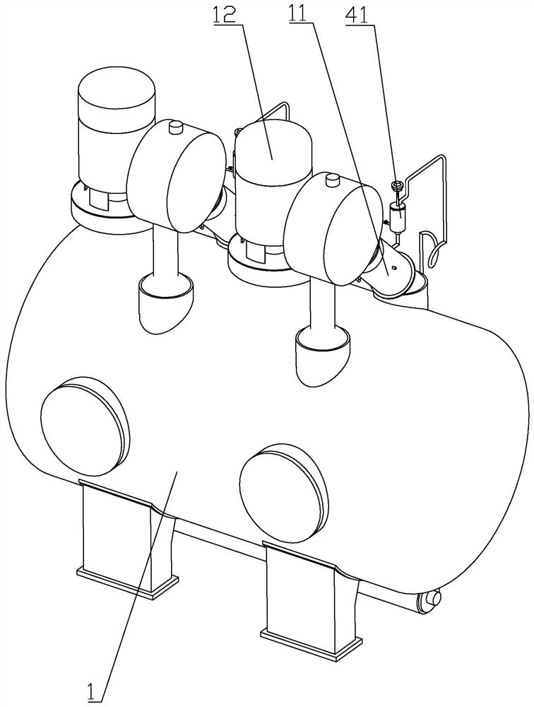

Image

  • Airflow dyeing machine
  • Airflow dyeing machine
  • Airflow dyeing machine

Examples


Embodiment Construction

[0036] The present invention will be described in detail below in conjunction with the accompanying drawings and embodiments.

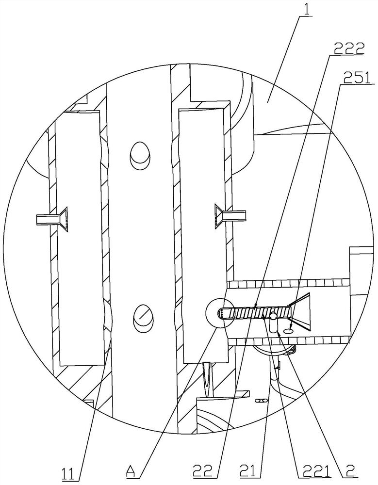
[0037] Such as figure 1 , figure 2 As shown, an airflow dyeing machine includes a machine body 1 , a nozzle housing 11 communicating with the machine body 1 , a fan 12 communicating with the nozzle housing 11 , and a return assembly 2 arranged on the nozzle housing 11 . When the cloth circulated in the machine body 1 passes through the nozzle housing 11, the atomized dye in the nozzle housing 11 is sprayed on the cloth under the air pressure of the fan 12, thereby dyeing the cloth.

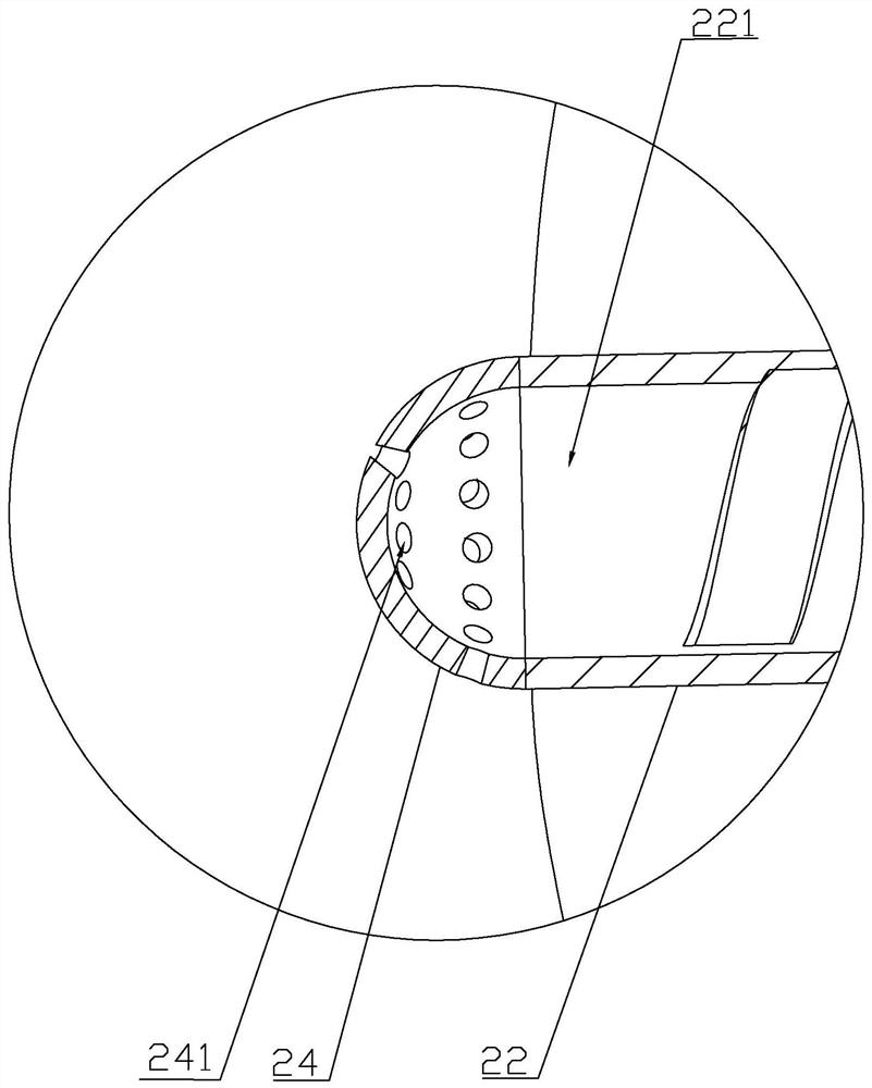
[0038] The return assembly 2 includes a drainage pipe 21 communicating with the lowest part of the inner wall of the nozzle housing 11, and a nozzle 22 arranged on the air outlet of the fan 12. through hole 221 . The drainage tube 21 is in the shape of a cylinder, one end of which passes through the nozzle housing 11 and the end opening is located at the bottom of the n...


PUM


Abstract

The invention discloses an airflow dyeing machine and relates to the technical field of textile processing equipment. The machine comprises a machine body, a spray nozzle shell communicated with the machine body, a fan communicated with the spray nozzle shell and a backflow assembly arranged on the spray nozzle shell; the backflow assembly comprises a drainage pipe communicated with the lowest portion of the inner wall of the spray nozzle shell and a spray nozzle arranged at an air outlet of the fan; the drainage pipe is communicated with the spray nozzle, and a through hole formed in the airdirection is formed in the spray nozzle. According to the scheme, since the air pressure of the through hole is lowered through the airflow of the air outlet, the drainage pipe can pump liquid dye inthe spray nozzle shell to the spray nozzle, the dye is blown away by the airflow and driven to be atomized, and liquid dye is reduced; therefore, the fluid-shaped dye is atomized again for airflow dyeing, the utilization rate of the dye is increased, and the airflow dyeing efficiency is improved.

Description

technical field [0001] The invention relates to the technical field of textile processing equipment, more specifically, it relates to an air flow dyeing machine. Background technique [0002] At present, compared with the traditional liquid flow dyeing machine, the air flow dyeing machine circulates the fabric by means of the gas channel containing moisture or water vapor, and does not need dyeing liquid or water medium to transport the fabric. Its biggest feature is that it reduces the dye, chemical Auxiliary and energy consumption. [0003] The Chinese invention whose notification number is CN102828367B discloses a novel multi-tube independent air supply air flow dyeing machine, which includes a main cylinder, a lifting drum, two or more blowers and nozzle combinations independently connected thereto. The fan is placed on the top of the main cylinder, the outlet of the fan is connected to the air inlet of the nozzle assembly, the outlet pipe of the fan reaches the nozzle ...

Claims


Application Information

Patent Timeline
Patent Type & Authority Patents(China)
IPC IPC(8): D06B1/02D06B23/20
CPCD06B1/02D06B23/20
Inventor 洪文龙
Owner 绍兴柯桥展望印染有限公司
Learn More