Rotary multiport switch

A rotary and switch technology, applied in the direction of electric switches, electrical components, circuits, etc.

Inactive Publication Date: 2019-02-12
安徽银点电子科技有限公司
View PDF0 Cites 2 Cited by
  • Summary
  • Abstract
  • Description
  • Claims
  • Application Information

AI Technical Summary

Problems solved by technology

[0005] The purpose of the present invention is to provide a rotary multi-position switch to solve the problem that the existing switch can only control one circuit

Method used


Image

  • Rotary multiport switch
  • Rotary multiport switch
  • Rotary multiport switch

Examples


Embodiment

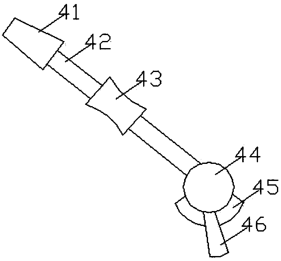
[0028] The rotary multi-position switch of this embodiment includes a bottom cover 6, a hemispherical housing 1 is clamped on the upper side of the bottom cover 6, and a plurality of static contacts 2 are hinged in the side wall of the housing 1 ; An arc-shaped inner guide frame 5 is clamped on the upper side of the bottom cover 6, and the inner absorbing part 5 is located in the inner cavity of the shell 1; a plurality of electromagnets are clamped on the inner guide frame 5 7. A coil is wound on the outside of the electromagnet 7; one of the electromagnets 7 and one of the static contacts 2 are aligned along the radial direction of the housing 1;

[0029] On the lower side of the bottom cover 6, a terminal block 3 is clipped, and the wires passing through the terminal block 3 are respectively electrically connected to the coils; a movable contact 4 is hinged in the bottom cover 6, The upper part of the movable contact 4 is rotatably arranged in the housing 1 ; the upper end ...


PUM


Abstract

The invention discloses a rotary multiport switch, which comprises a bottom cover, wherein a hemispherical outer shell is connected to the upper side of the bottom cover in a clamped manner, and a plurality of static contact heads are connected to the side wall of the outer shell in a hinged manner; an arc-shaped inner guiding frame is connected to the upper side of the bottom cover in a clamped manner, and the inner absorption piece is positioned in an inner cavity of the outer shell; a plurality of electromagnets are connected to the inner guiding frame in a clamped manner, and coils are wound to the outer sides of the electromagnets; the electromagnets and the static contact heads are aligned along the radial direction of the outer shell; a patch board is connected to the lower side ofthe bottom cover in a clamped manner, and wires penetrating through the patch board are respectively electrically connected to the coils; a movable contact head is connected to the bottom cover in a hinged manner, and the upper part of the movable contact head is arranged in the outer shell in a rotary manner; and the upper end of the movable contact head is close to the inner wall of the outer shell. The rotary multiport switch can selectively control a plurality of circuits, and has high integration level, so that the needs of multi-channel control are met.

Description

technical field [0001] The invention relates to the technical field of switches, in particular to a rotary multi-position switch. Background technique [0002] In the field of industrial automation all over the world, especially in the intelligent electrification industry, more and more electronic switch controls are used. Existing electrical equipment needs to control multiple electronic components to achieve multiple functions. However, the existing switch is usually a single contact, which can only switch one circuit at a time, and cannot control multiple circuits, and the integration level of the switch is relatively low. [0003] When it is necessary to control multiple circuits, multiple switches need to be provided, and the structure of the switch will be very complicated, resulting in a large structure, occupying a lot of space, and being inconvenient to install and use; It is easy to cause mutual interference and affect normal use. A single switch can only control...

Claims


Application Information

Patent Timeline
IPC IPC(8): H01H19/04H01H19/10H01H19/20
CPCH01H19/04H01H19/10H01H19/20
Inventor 冯明铎张家植
Owner 安徽银点电子科技有限公司
Why Eureka
Try Eureka