Sensor Integration for Clutch Disconnectors

A clutch and separator technology, applied in clutches, fluid-driven clutches, non-mechanical-driven clutches, etc., can solve the problems of a large number of separate components, high cost, and large structural space requirements

Active Publication Date: 2021-11-30
SCHAEFFLER TECH AG & CO KG
View PDF12 Cites 0 Cited by
  • Summary
  • Abstract
  • Description
  • Claims
  • Application Information

AI Technical Summary

Problems solved by technology

[0004] However, a disadvantage of the solutions known from the prior art is that at least a part of the sensor or the sensor unit is arranged outside the housing of the clutch release, as a result of which the installation space requirement becomes extremely large.
In addition, a large number of individual components are required, resulting in high costs
A further problem in existing solutions is the relatively large tolerance chain and thus the inaccuracy in displacement measurement

Method used


Image

  • Sensor Integration for Clutch Disconnectors
  • Sensor Integration for Clutch Disconnectors
  • Sensor Integration for Clutch Disconnectors

Examples


Embodiment Construction

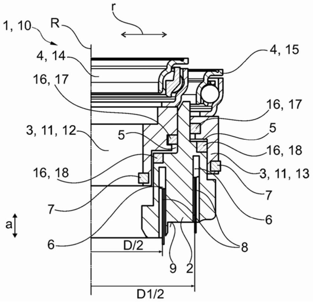
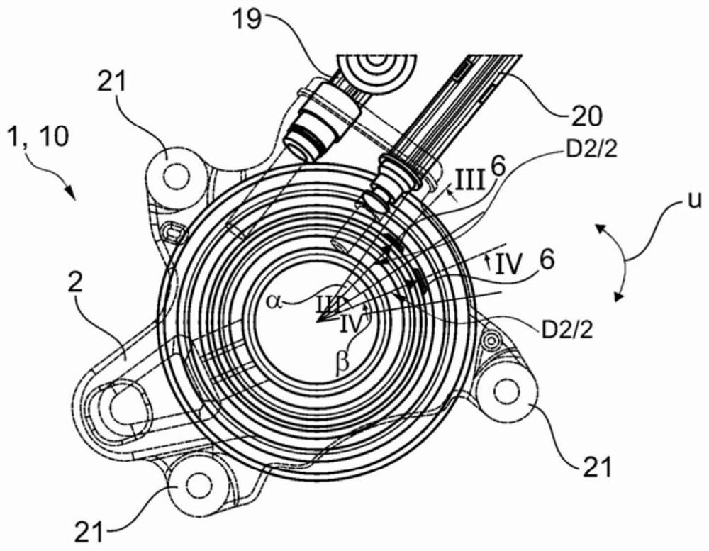
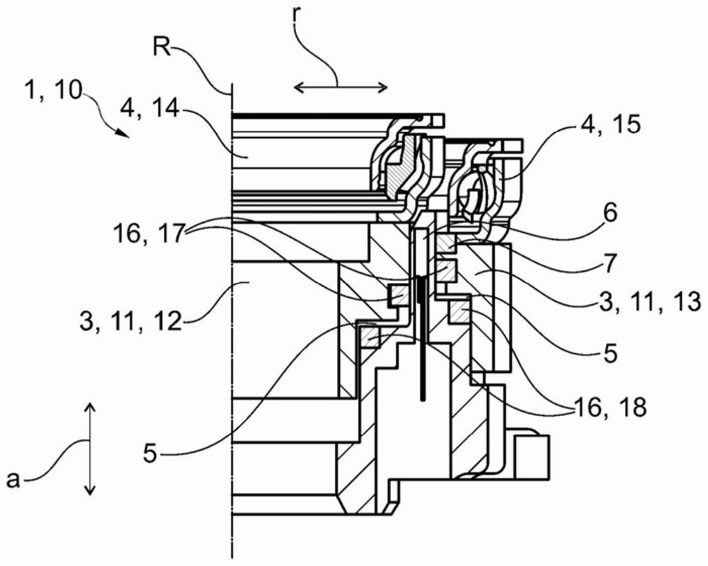
[0026] figure 1 An exemplary first embodiment of the clutch release 1 is shown. The clutch release 1 has a housing 2 (see also figure 2 ), in which the two pistons 3, 3 are accommodated. Pistons 3 , 3 are axially displaceable in housing 2 in order to actuate a release bearing 4 in each case. In order to move the piston 3 axially in the housing 2 , each piston 3 forms with the housing 2 a pressure chamber 5 which can be pressurized by means of hydraulic fluid, whereby the piston 3 can be moved along the axis of rotation R .

[0027] Two sensors 6 are accommodated in the housing 2 , which are used to detect the position of a piston 3 in each case. For this, a magnet 7 is attached to each piston 3 , the position of which can be determined via the associated sensor 6 . The sensor 6 is accommodated in the housing 2 in a recess 8 which is open towards the side 9 of the housing 2 facing away from the release bearing. The sensor 6 can thus be inserted into the housing 2 from th...


PUM


Abstract

The invention relates to a clutch release (1) for actuating a clutch in a drive train of a motor vehicle, said clutch release having a housing (2), at least one piston for displacing a release bearing (4) (3) is housed in the housing in an axially movable manner, and the piston and the housing (2) form a pressure chamber (5), wherein a sensor (6) is fixed on the housing (2), the sensor Designed for position detection of a magnet (7) fixed to the piston, in which a recess (8) is formed in the housing (2) fitted with a sensor (6) from the side (9) remote from the release bearing ).

Description

technical field [0001] The invention relates to a preferably hydraulic clutch release for actuating a clutch in a power train of a motor vehicle, for example a single clutch or a double clutch, for example a single output cylinder or a concentric slave cylinder (CSC) or a dual output cylinder or a dual CSC, the clutch release has a housing in which at least one piston for displacing the release bearing is accommodated / arranged axially movably, and the piston and the housing form a pressure chamber, wherein in On the housing is fixed a sensor designed for position detection of a magnet fixed to the piston. Background technique [0002] Various separation systems or clutch releases are already known from the prior art. [0003] DE 10 2010 035 137 D4 discloses a dual clutch actuation device for actuating a dual clutch in a dual clutch transmission. The dual clutch operating device includes a housing fixedly mounted on the dual clutch transmission and defining first and second...

Claims


Application Information

Patent Timeline
Patent Type & Authority Patents(China)
IPC IPC(8): F16D25/08F16D25/12
CPCF16D25/08F16D25/12F16D25/083F16D25/10F16D2300/18
Inventor 多丽丝·马里亚·罗伊特菲利普·瓦格纳
Owner SCHAEFFLER TECH AG & CO KG
Why Eureka
Try Eureka