A catalytic cracking energy analysis method and device

A catalytic cracking unit and catalytic cracking technology, applied in general control systems, program control, instruments, etc., can solve the problem of inability to fully and accurately reflect changes in new raw materials and new processes, inability to calculate energy consumption of catalytic cracking units, and unfavorable for energy saving of excavation devices Potential and other issues to achieve the effect of tapping energy-saving potential

Active Publication Date: 2020-11-10
CHINA PETROLEUM & CHEM CORP +1
View PDF4 Cites 0 Cited by
  • Summary
  • Abstract
  • Description
  • Claims
  • Application Information

AI Technical Summary

Problems solved by technology

In the past 10 years, the catalytic cracking technology has undergone major changes, and its operating conditions, raw material properties, product distribution, product standards, etc. Make accurate calculations of energy consumption
In addition, the existing benchmark energy consumption calculation method has made a series of calculation regulations during the calculation, and it is impossible to reasonably calculate the energy consumption according to the individual conditions such as the actual process level and processing plan of each device
With the emergence of various new technologies, existing energy consumption calculation methods cannot completely and accurately reflect changes in new raw materials and new processes
Therefore, it cannot reflect the minimum energy consumption that the device can theoretically achieve, which is not conducive to excavating the energy saving potential of the device

Method used


Image

  • A catalytic cracking energy analysis method and device
  • A catalytic cracking energy analysis method and device
  • A catalytic cracking energy analysis method and device

Examples


Embodiment Construction

[0053] In order to make the purpose, technical solutions and advantages of the embodiments of the present invention clearer, the technical solutions in the embodiments of the present invention will be clearly and completely described below in conjunction with the drawings in the embodiments of the present invention. Obviously, the described embodiments It is a part of embodiments of the present invention, but not all embodiments. Based on the embodiments of the present invention, all other embodiments obtained by persons of ordinary skill in the art without creative efforts fall within the protection scope of the present invention.

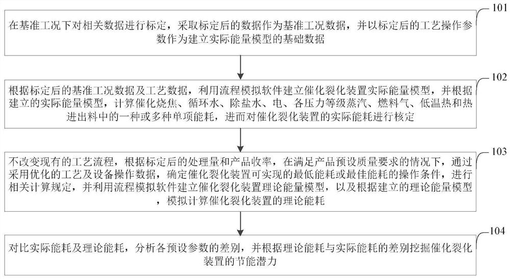
[0054] An embodiment of the present invention provides a method for analyzing energy consumption of catalytic cracking, see figure 1 , the method includes the following steps:

[0055] Step 101: Calibrate the relevant data under the reference working condition, take the calibrated data as the reference working condition data, and use the calibrat...


PUM


Abstract

The invention provides a catalytic-cracking energy use analysis method and device. The method comprises: establishing an actual energy model of a catalytic-cracking device according to benchmark working condition data and technology data after calibration, and verifying actual energy consumption of the catalytic-cracking device; determining an operation condition of minimum energy consumption which can be realized by the catalytic-cracking device through use of optimized technology and equipment operation data in a case, where a preset product quality requirement is met according to processingquantity and product yield after calibration without changing an existing technology process, carrying out relevant calculation regulation, establishing a theoretical energy model of the catalytic-cracking device, and carrying out simulation calculation on the theoretical energy consumption of the catalytic-cracking device; and mining energy saving potentials of the catalytic-cracking device through difference comparison of the actual energy consumption and the theoretical energy consumption. According to the method, firstly the lowest energy consumption which can be achieved theoretically bythe catalytic-cracking device can be obtained, then the theoretical minimum energy consumption can be compared with the actual energy consumption, and thus mining of the energy saving potentials of the catalytic-cracking device is facilitated.

Description

technical field [0001] The invention relates to the technical field of refinery process energy consumption calculation, in particular to a catalytic cracking energy consumption analysis method and device. Background technique [0002] With the development of large-scale, integrated and complex petrochemical process production equipment, enterprises have also put forward higher and higher requirements for the control and optimization of the production process, especially the demand for energy-saving and emission reduction of production enterprises is increasingly valued. Advanced control strategies represented by predictive control and real-time optimization have been widely used. Advanced control technology can improve the stability rate of production equipment and achieve "card edge" optimization, so as to ensure product quality, increase productivity, reduce energy consumption, reduce accidents and avoid shutdown losses, and the economic benefits are obvious. [0003] Cat...

Claims


Application Information

Patent Timeline
Patent Type & Authority Patents(China)
IPC IPC(8): G05B19/042
CPCG05B19/0428G05B2219/24024
Inventor 张伟王红涛胡珺张英郭土胡丞
Owner CHINA PETROLEUM & CHEM CORP
Why Eureka
Try Eureka