A gear high-precision hobbing fixture and its use method
A hobbing jig, high-precision technology, applied in the field of high-precision gear hobbing jigs, can solve the problems of gear clamping and dismantling, time-consuming and labor-intensive steps, and achieve low skill requirements, simple operation, and time-saving disassembly Labor-saving effect
- Summary
- Abstract
- Description
- Claims
- Application Information
AI Technical Summary
Problems solved by technology
Method used
Image
Examples
Embodiment 1
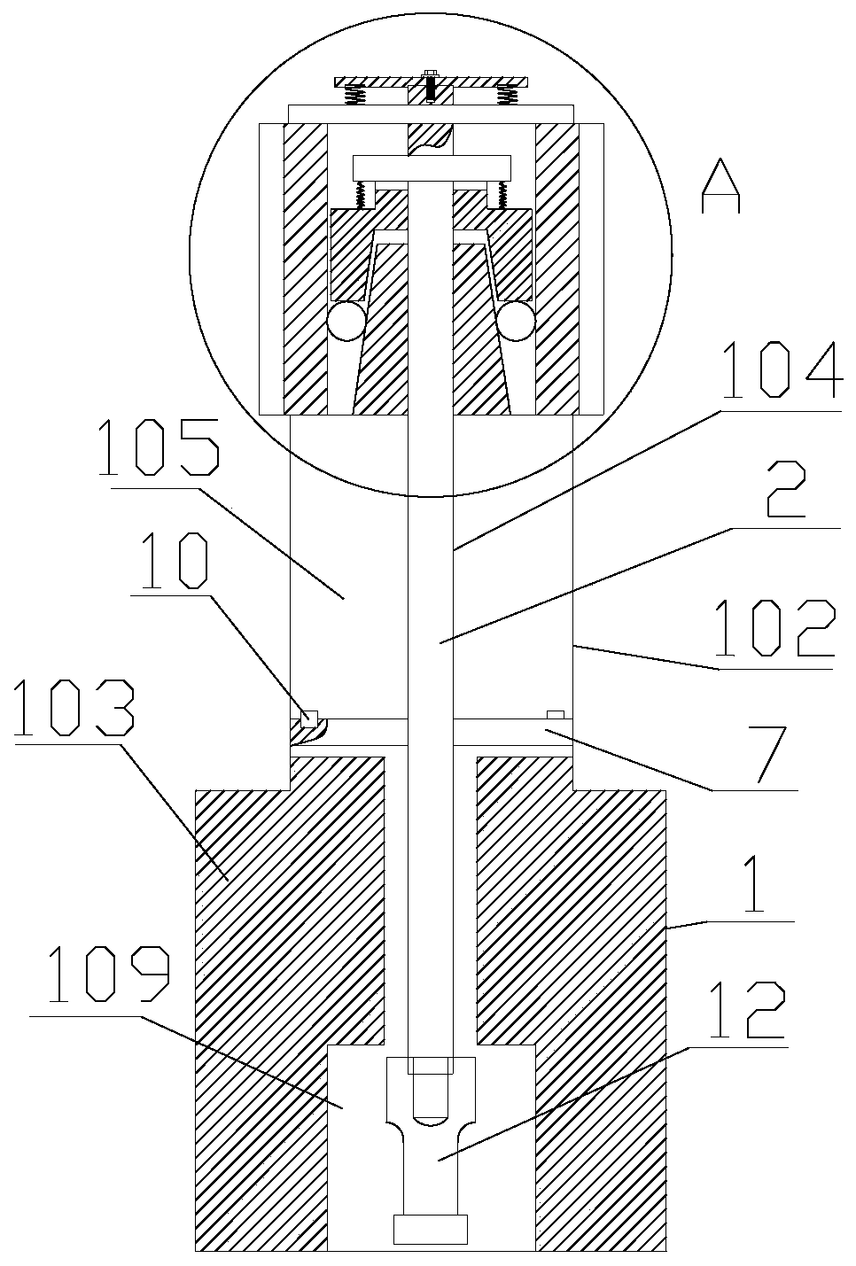
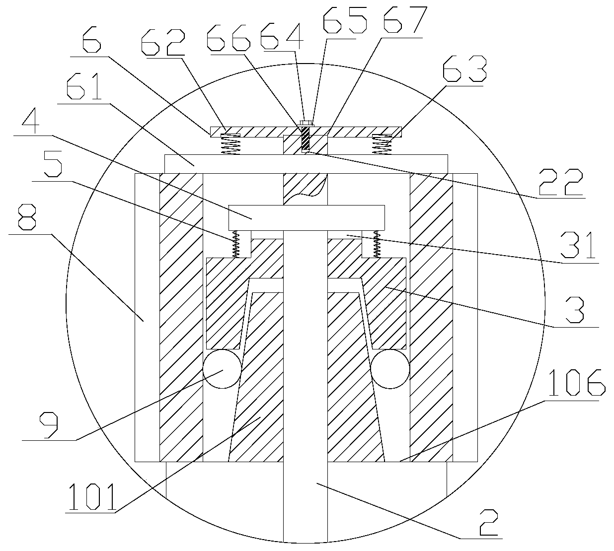
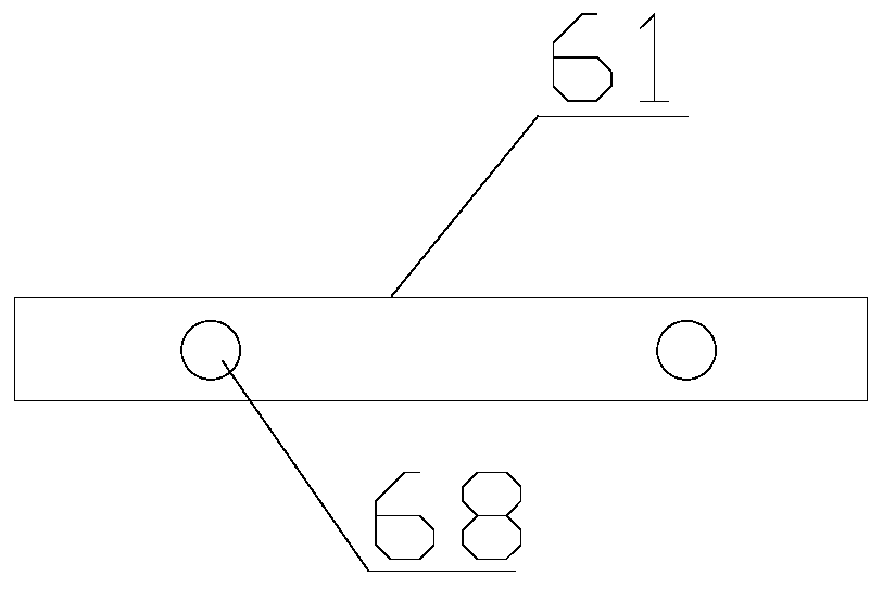
[0013] Embodiment 1: with reference to attached Figure 1-Figure 5 . A gear high-precision hobbing fixture, including a cone seat 1, the cone seat 1 is composed of a conical shaft section 101, a first circular shaft section 102 and a second circular shaft section 103 arranged in sequence from top to bottom and The centerlines of the tapered shaft section 101, the first circular shaft section 102, and the second circular shaft section 103 coincide, and the tapered shaft section 101, the first circular shaft section 102, and the second circular shaft section 103 are in the form of Overall structure and the diameter of the first circular shaft section 102 is greater than the diameter of the largest circle of the tapered shaft section 101 and the diameter of the first circular shaft section 102 is smaller than the diameter of the second circular shaft section 103, the cone The upper end surface of the seat 1 is provided with a through hole 104 passing through the upper and lower ...
Embodiment 2
[0014] Embodiment 2: On the basis of Embodiment 1, a method of using a high-precision gear hobbing jig, step 1, before the gear 8 is hobbed, the first pressure plate 61 of the elastic pressure plate 6 is first passed through the pressure plate Pull out the hole 23, then place the gear 8 on the first shoulder 106 of the cone seat 1, then start the hydraulic lifting mechanism, and the hydraulic lifting mechanism drives the threaded connecting rod 12 to go up until the top sleeve 3 leaves the inner hole of the gear 8 and the gear 8 is on the The gap between the end surface and the lower end surface of the top sleeve 3 can pass through the steel ball 9; Step 2, put the steel ball 9 into the gap between the upper end surface of the gear 8 and the lower end surface of the top sleeve 3 and insert the first pressure plate 61 back into the pressure plate through the gap. In the hole 23, start the hydraulic lifting mechanism afterwards, and the hydraulic lifting mechanism drives the thre...
PUM
 Abstract
Description
Claims
Application Information
 - R&D
- Intellectual Property
- Life Sciences
- Materials
- Tech Scout
- Unparalleled Data Quality
- Higher Quality Content
- 60% Fewer Hallucinations
Browse by: Latest US Patents, China's latest patents, Technical Efficacy Thesaurus, Application Domain, Technology Topic, Popular Technical Reports.
© 2025 PatSnap. All rights reserved.Legal|Privacy policy|Modern Slavery Act Transparency Statement|Sitemap|About US| Contact US: help@patsnap.com


