
Camera device and video viewing method thereof

A camera and video technology, which is applied in the computer field, can solve the problems of uncontrollable time, camera-side WiFi can not work independently, and wait for a long time, so as to optimize hardware design and connection logic, speed up real-time video speed, and quickly watch video. Effect

Active Publication Date: 2019-01-18
ANKER INNOVATIONS TECH CO LTD
View PDF6 Cites 0 Cited by
  • Summary
  • Abstract
  • Description
  • Claims
  • Application Information

AI Technical Summary

Problems solved by technology

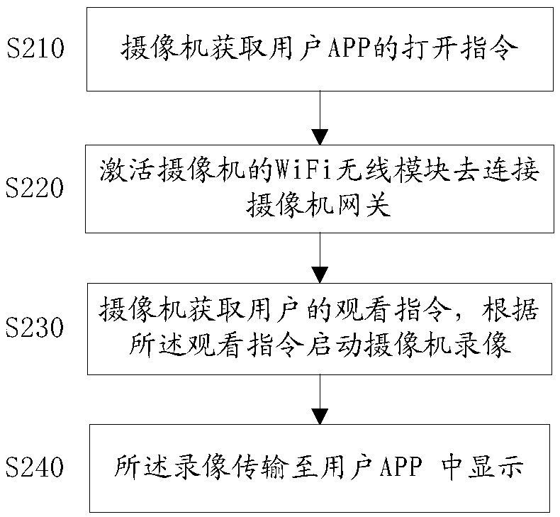
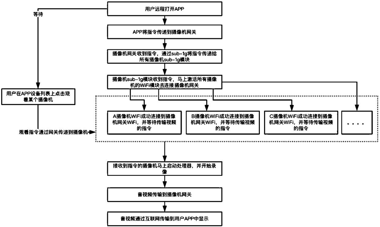
[0003] However, the APP needs to receive an instruction to activate the camera when the user clicks on a specific camera. Otherwise, all cameras will be activated before receiving the instruction, which will easily cause the camera to start in advance, increase battery power consumption, and the user will not view all the cameras every time. Camera; and the camera starts the controller and WiFi after receiving the command, because WiFi depends on the controller to start and connect, so the working status of WiFi is connected in series, you need to start WiFi, then connect the WiFi to the gateway, and then transmit the video, and the middle one The time of the WiFi connection gateway step is very uncontrollable, because the connection efficiency is affected by the WiFi signal strength and interference, resulting in an uncontrollable time for the Unicom camera. If it is fast, the video can be passed in 1-2 seconds, and if it is slow, it will take 5 seconds or even longer
[0004] Therefore, in the prior art, there is a problem that the WiFi at the camera end cannot work independently, and needs to rely on the controller to drive the work. In this way, when the user remotely watches the camera through the APP, it needs to wait for a long time, resulting in a poor experience

Method used


Image

  • Camera device and video viewing method thereof
  • Camera device and video viewing method thereof
  • Camera device and video viewing method thereof

Examples


Embodiment Construction

[0030] In order to make the objects, technical solutions and advantages of the present invention more apparent, exemplary embodiments according to the present invention will be described in detail below with reference to the accompanying drawings. Apparently, the described embodiments are only some embodiments of the present invention, rather than all embodiments of the present invention, and it should be understood that the present invention is not limited by the exemplary embodiments described here. Based on the embodiments of the present invention described in the present invention, all other embodiments obtained by those skilled in the art without creative effort shall fall within the protection scope of the present invention.

[0031] Refer below figure 1 A schematic structural diagram of a camera device for implementing an embodiment of the present invention will be described. The camera installation includes a camera and a camera gateway, wherein,

[0032] The camera ...


PUM


Abstract

The present invention provides a camera device and a video viewing method, and the device comprises a camera and a camera gateway. The camera comprises a camera unit, a first controller, and a first communication unit. The camera unit is connected with the first controller, and the first controller is connected with the first communication a unit. The first communication unit is configured to communicate with the camera gateway, and the camera gateway includes a second communication unit and a second controller, wherein the second controller is connected with the second communication unit, andthe second communication unit is configured to communicate with the camera. According to the invention, the device can achieve the purpose of speeding up remote viewing of a real-time video speed byoptimizing hardware design and connection logic without greatly increasing camera battery consumption, gives consideration to low power consumption and fast viewing of a video, and improves user experience.

Description

technical field [0001] The present application relates to the field of computer technology, in particular to a camera device and a video watching method thereof. Background technique [0002] As modern people pay more attention to security, more and more home security cameras are used, and the technology is constantly developing. One of the development directions is battery security cameras. As the name implies, a battery security camera refers to a built-in battery in the camera, which sleeps when not working and activates full functions when working to achieve long standby. In order to prolong the standby and use time of the camera, on the one hand, a battery with a higher capacity is used, and on the other hand, the power consumption of the camera is reduced. An important aspect of reducing the power consumption of the camera is to reduce the standby power consumption. The main way to reduce the standby power consumption is to turn off the processor, image sensor and com...

Claims


Application Information

Patent Timeline
Patent Type & Authority Applications(China)
IPC IPC(8): H04N5/232H04N5/225
CPCH04N23/50H04N23/661
Inventor 李琳琅
Owner ANKER INNOVATIONS TECH CO LTD
Learn More