Needle plate structure for silk fabric printing and dyeing machine

A technology for printing and dyeing machines and silk fabrics, which is applied to general parts of printing machinery, printing machines, printing, etc. It can solve problems such as poor anti-vibration performance, easily damaged needle plate structure due to vibration, and steel needles touched by maintenance personnel. Excellent vibration performance, improved anti-vibration performance, and avoiding vibration damage

Inactive Publication Date: 2019-01-18
湖州飞顺丝绸有限公司
View PDF0 Cites 0 Cited by
  • Summary
  • Abstract
  • Description
  • Claims
  • Application Information

AI Technical Summary

Problems solved by technology

The needle plate structure used in the existing silk fabric printing and dyeing machine has the problem of poor anti-vibration performance, and because the existing silk fabric printing and dyeing machine works, the motor of the existing silk fabric printing and dyeing machine runs and generates a large vibration, so that the existing silk fabric printing and dyeing machine The silk fabric printing and dyeing machine produces relatively large vibrations, so the needle plate structure used in the existing silk fabric printing and dyeing machine is easily damaged by vibration
[0003] The needle plate structure used in the existing silk fabric printing and dyeing machine is composed of a needle plate and a needle plate fixing seat, and a number of steel needles are densely covered on the needle plate, and are fixed on the needle plate fixing seat by screws. On the upper surface of the needle plate, because the steel needles are relatively sharp, when disassembling the needle plate, it is easy for the maintenance personnel to touch the steel needles, resulting in the maintenance personnel being stabbed
[0004] Therefore, the needle plate structure used in the existing silk fabric printing and dyeing machine not only has the problem of poor vibration resistance and is easy to cause vibration damage, but also when disassembling the needle plate, it is easy for the maintenance personnel to touch the steel needles, resulting in the maintenance personnel being stabbed. Injury situation

Method used


Image

  • Needle plate structure for silk fabric printing and dyeing machine
  • Needle plate structure for silk fabric printing and dyeing machine
  • Needle plate structure for silk fabric printing and dyeing machine

Examples


Embodiment Construction

[0021] Below in conjunction with accompanying drawing and embodiment the present invention will be further described, but not as the basis for limiting the present invention.

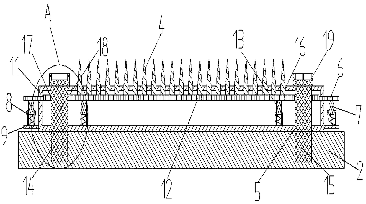
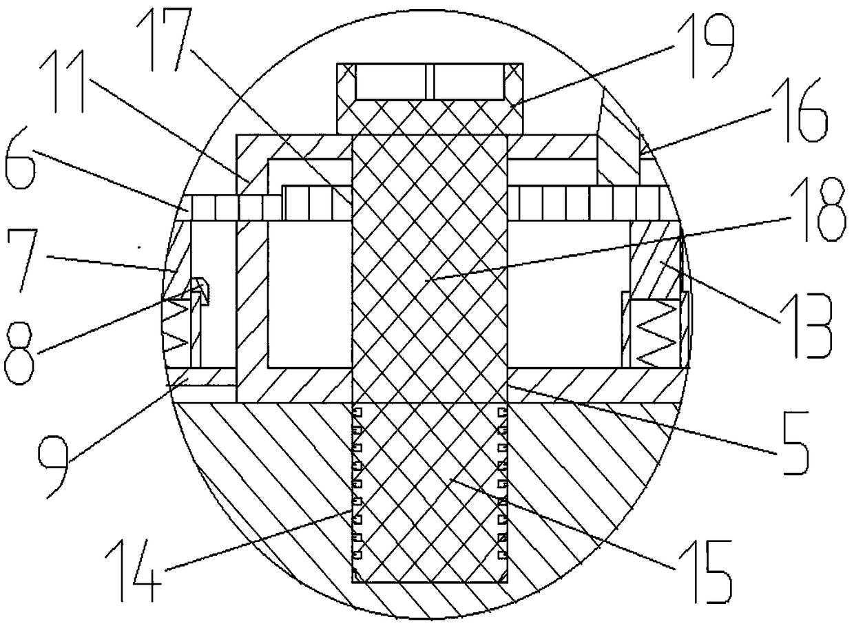
[0022] Example. The needle plate structure used in silk fabric printing and dyeing machine is as follows: Figure 1-4 As shown, it includes a needle plate 1, and a needle plate fixing seat 2 is arranged under the needle plate 1; the needle plate 1 includes a steel needle hollow plate 11, and a steel needle lifting plate 12 is arranged in the cavity of the steel needle hollow plate 11; The steel needle hollow plate 11 is provided with the first vertical through hole 5, the steel needle hollow plate 11 upper end is provided with a steel needle matching hole 16, and the steel needle hollow plate 11 left and right ends are all provided with a sliding through groove 10; The lifting plate 12 is provided with a second vertical through hole 17, the upper end of the steel needle lifting plate 12 is provided wit...


PUM


Abstract

The invention discloses a needle plate structure for a silk fabric printing and dyeing machine, which comprises a needle plate (1), wherein a needle plate fixing seat (2) is arranged below the needleplate (1) ; the needle plate (1) comprises a steel needle hollow plate (11), and a steel needle lifting plate (12) is arranged in the inner cavity of the steel needle hollow plate (11) ; the upper endof the steel needle hollow plate (11) is provided with a steel needle matching hole (16), and the left end and right end of the steel needle hollow plate (11) are both provided with a sliding throughgroove (10) ; the upper end of the steel needle lifting plate (12) is provided with a steel needle (4) which is connected with the steel needle matching hole (16), and the left end and right end of the steel needle lifting plate (12) are both provided with a sliding block (6) which penetrate through and is connected with the sliding through groove (10). The device not only has the advantages of better vibration resistance and capability of avoiding vibration damage, but also can avoid the situation that maintenance personnel touch the steel needle, which causes the maintenance personnel to bestabbed and injured when the needle plate is assembled and disassembled.

Description

technical field [0001] The invention relates to the technical field of needle plates for silk fabric printing and dyeing machines, in particular to a needle plate structure for silk fabric printing and dyeing machines. Background technique [0002] Needle bar structures for silk dyeing machines are used to lay flat textiles. The needle plate structure used in the existing silk fabric printing and dyeing machine has the problem of poor anti-vibration performance, and because the existing silk fabric printing and dyeing machine works, the motor of the existing silk fabric printing and dyeing machine runs and generates a large vibration, so that the existing silk fabric printing and dyeing machine The silk fabric printing and dyeing machine produces relatively large vibrations, so the needle plate structure used in the existing silk fabric printing and dyeing machine has the situation that the vibration is easy to be damaged. [0003] The needle plate structure used in the exi...

Claims


Application Information

Patent Timeline
IPC IPC(8): D06B23/04B41F23/00
CPCD06B23/04B41F23/00
Inventor 姚红根
Owner 湖州飞顺丝绸有限公司
Why Eureka
Try Eureka