Torque control method for screwing bolts
A torque control and bolt technology, applied in the field of torque control screwing and screwing bolts, can solve the problems of wasting time, slow speed, low work efficiency, etc.
- Summary
- Abstract
- Description
- Claims
- Application Information
AI Technical Summary
Problems solved by technology
Method used
Image
Examples
Embodiment 1
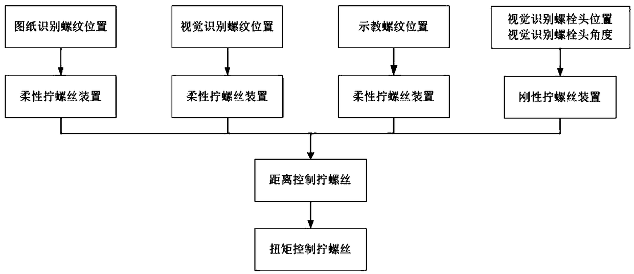
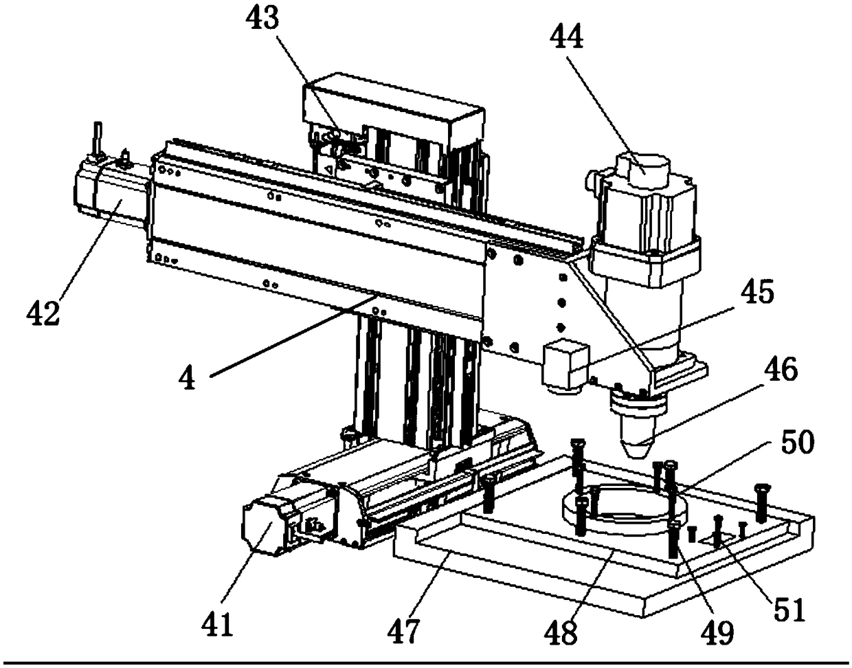
[0050] Such as Figure 1-Figure 7 As shown, the torque control bolt tightening method provided in this embodiment includes a Cartesian coordinate bolt machine 4, a calibration plate 47 and a control system connected to the Cartesian coordinate bolt machine 4. The Cartesian coordinate bolt machine 4 is provided with three-axis linkage, and the three-axis linkage Including the X-axis 41, the Y-axis 42 arranged on the X-axis 41, the Z-axis 43 arranged on the Y-axis 42 and the C-axis 44 at one end of the Z-axis 43, including the following steps:
[0051] Step 1: Fix the workpiece 48 according to the calibration plate 47, such as Figure 5 with Image 6 As shown, the workpiece is fixed on the calibration plate at any angle and position;
[0052] Step 2: An industrial camera 45, a vision system connected to the industrial camera 45, a host system, and a drawing of the workpiece 48 imported into the host system are installed on the Cartesian coordinate bolt machine 4, and the workpie...
Embodiment 2
[0078] Such as Figure 1-Figure 4 with Figure 8 As shown, the torque control bolt tightening method provided in this embodiment includes a Cartesian coordinate bolt machine 4, a calibration plate 47 and a control system connected to the Cartesian coordinate bolt machine 4. The Cartesian coordinate bolt machine 4 is provided with three-axis linkage, and the three-axis linkage Including the X-axis 41, the Y-axis 42 arranged on the X-axis 41, the Z-axis 43 arranged on the Y-axis 42 and the C-axis 44 at one end of the Z-axis 43, including the following steps:
[0079] Step 1: fix the workpiece 48 according to the calibration plate 47;
[0080] Step 2: An industrial camera 45 and a vision system connected to the industrial camera 45 are installed on the rectangular coordinate bolt machine 4. The industrial camera 45 takes pictures of the workpiece 48 within the scope of the calibration plate 47 to generate an image, and the visual recognition is grouped into the vision system acc...
Embodiment 3
[0106] Such as Figure 1-Figure 4 with Figure 9 As shown, the torque control bolt tightening method provided in this embodiment includes a Cartesian coordinate bolt machine 4, a calibration plate 47 and a control system connected to the Cartesian coordinate bolt machine 4. The Cartesian coordinate bolt machine 4 is provided with three-axis linkage, and the three-axis linkage Including the X-axis 41, the Y-axis 42 arranged on the X-axis 41, the Z-axis 43 arranged on the Y-axis 42 and the C-axis 44 at one end of the Z-axis 43, including the following steps:
[0107] Step 1: fix the workpiece 48 according to the calibration plate 47;
[0108] Step 2: Carry out teaching identification grouping and group numbering for the specifications of the threads on all workpieces 48, the position coordinates of the threads, and the number of threads;
[0109] Step 3: The control system performs overall path planning for the threads of all groups: Manually operate the Cartesian bolt machine...
PUM
 Abstract
Description
Claims
Application Information
 - Generate Ideas
- Intellectual Property
- Life Sciences
- Materials
- Tech Scout
- Unparalleled Data Quality
- Higher Quality Content
- 60% Fewer Hallucinations
Browse by: Latest US Patents, China's latest patents, Technical Efficacy Thesaurus, Application Domain, Technology Topic, Popular Technical Reports.
© 2025 PatSnap. All rights reserved.Legal|Privacy policy|Modern Slavery Act Transparency Statement|Sitemap|About US| Contact US: help@patsnap.com


