Multi-layer hog house

A multi-layer pig house, rectangular technology, applied in the field of pig raising equipment, can solve the problems of low efficiency, a lot of manpower and high cost, and achieve the effects of reducing production costs, improving production efficiency and ingredient quality, and being easy to discharge.

Inactive Publication Date: 2019-01-18
郏县全民牧业有限公司
View PDF0 Cites 3 Cited by
  • Summary
  • Abstract
  • Description
  • Claims
  • Application Information

AI Technical Summary

Problems solved by technology

It requires a lot of manpower to complete the breeding, which is inefficient and costly, and cannot meet the needs of the market

Method used


Image

  • Multi-layer hog house
  • Multi-layer hog house
  • Multi-layer hog house

Examples


Embodiment 1

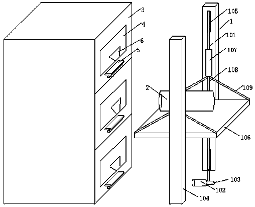
[0022] Such as Figure 1 to Figure 7 As shown, a multi-storey pig house includes a plurality of feeding rooms 3 arranged sequentially from top to bottom, one side of the feeding room 3 is provided with a transport mechanism 1, and the side wall of the feeding room 11 close to the transport mechanism is provided with a transport port 4. A feed trough 6 is arranged in the feeding room 3 , and one end of the feed trough 6 is set close to the transport port 4 .

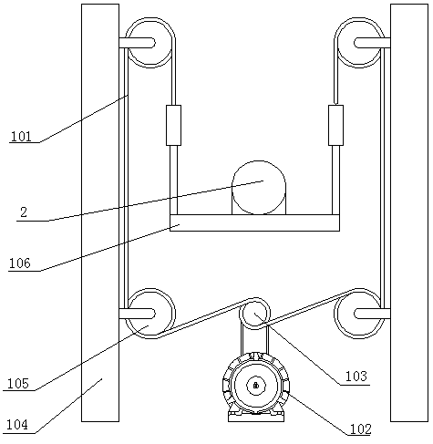
[0023] The transport mechanism 1 comprises a steel wire rope 101, a motor 102, an output shaft 103 of a reducer connected to the motor 102, two vertical columns 104 arranged in parallel at intervals, and a rectangular object platform 106 arranged between the two vertical columns 104. A connecting rod 107 is arranged on the top of the two ends of the two upright columns 104 close to the object platform 106, and a vertical rod 108 and two inclined rods 109 are arranged below each connecting rod 107. The vertical rod 108 and...

Embodiment 2

[0036] Such as Figure 1 to Figure 7 As shown, a multi-storey pig house includes a plurality of feeding rooms 3 arranged sequentially from top to bottom, one side of the feeding room 3 is provided with a transport mechanism 1, and the side wall of the feeding room 11 close to the transport mechanism is provided with a transport port 4. A feed trough 6 is arranged in the feeding room 3 , and one end of the feed trough 6 is set close to the transport port 4 .

[0037] The transport mechanism 1 comprises a steel wire rope 101, a motor 102, an output shaft 103 of a reducer connected to the motor 102, two vertical columns 104 arranged in parallel at intervals, and a rectangular object platform 106 arranged between the two vertical columns 104. A connecting rod 107 is arranged on the top of the two ends of the two upright columns 104 close to the object platform 106, and a vertical rod 108 and two inclined rods 109 are arranged below each connecting rod 107. The vertical rod 108 and...


PUM


Abstract

The invention provides a multi-layer hog house. The multi-layer hog house comprises feeding rooms which are arranged from top to bottom in sequence, a transportation mechanism is arranged on one sideof the feeding rooms, transportation openings are formed in the side walls, close to the transportation mechanism, of the feeding rooms, feed troughs are formed in the feeding rooms, and one end of each feed trough is close to the corresponding transportation opening. The transportation mechanism comprises a steel wire rope, a motor, a reducer output shaft connected with the motor, two upright columns and a rectangular bearing table, wherein the two upright columns are spaced and parallel, and the rectangular bearing table is arranged between the two upright columns. Each feed trough comprisesa trough body with an opening in the upper portion, wherein a base is arranged on the lower portion of the trough body, the four corners on the bottom of the trough body are fixedly connected with the base through vibrating springs respectively, a vibrating motor is arranged on the outer wall on the bottom of the trough body, and a dry material uniform-distribution mechanism is arranged above thetrough body. A material mixing mechanism is fixedly installed on the rectangular bearing table, the material mixing mechanism comprises a material mixing cylinder, a dry material storage hopper and aliquid material storage hopper are arranged above the material mixing cylinder, and a hinged base and a jack are arranged below the material mixing cylinder.

Description

technical field [0001] The invention relates to the technical field of pig raising equipment, in particular to a multi-storey pig house. Background technique [0002] Traditional pig houses are mostly single-story design, occupying a large area and low land utilization rate, which does not conform to the direction of the national land use and water and soil conservation policy. In order to alleviate the contradiction of large-scale and industrialized pig farming, multi-storey pig houses have emerged as the times require, making the pig houses develop in a spatial direction and reducing the area occupied by the pig houses. Although these multi-storey pig houses have solved the contradiction of difficult land for raising pigs, they have brought the problem of feeding inconvenience at the same time. At present, when feeding feed to pigs in multi-storey pig houses, the feed is manually carried, and then the feed is manually poured into the feeding trough, which requires more la...

Claims


Application Information

Patent Timeline
Patent Type & Authority Applications(China)
IPC IPC(8): A01K1/02A01K1/035A01K5/00A01K5/02
CPCA01K1/02A01K1/0356A01K5/002A01K5/02
Inventor 李全民
Owner 郏县全民牧业有限公司
Why Eureka
Try Eureka