
A photoelectric hybrid connector and connector assembly

A connector component and photoelectric hybrid technology, which is applied to the parts, connections, electrical components, etc. of the connection device, to achieve the effect of improving general performance, expanding the use place, and expanding the application place

Active Publication Date: 2019-01-15
CHINA AVIATION OPTICAL-ELECTRICAL TECH CO LTD
View PDF6 Cites 3 Cited by
  • Summary
  • Abstract
  • Description
  • Claims
  • Application Information

AI Technical Summary

Problems solved by technology

[0004] The object of the present invention is to provide a photoelectric hybrid connector that can only transmit optical signals or electrical signals, so as to solve the problem that the photoelectric hybrid connectors in the prior art can only transmit optical signals and electrical signals synchronously. The technical problem of using limitations; at the same time, the present invention also provides a connector assembly using the above-mentioned photoelectric hybrid connector

Method used


Image

  • A photoelectric hybrid connector and connector assembly
  • A photoelectric hybrid connector and connector assembly
  • A photoelectric hybrid connector and connector assembly

Examples


Embodiment Construction

[0036]The specific embodiments of the present invention will be further described below in conjunction with the accompanying drawings, but not limited thereto.

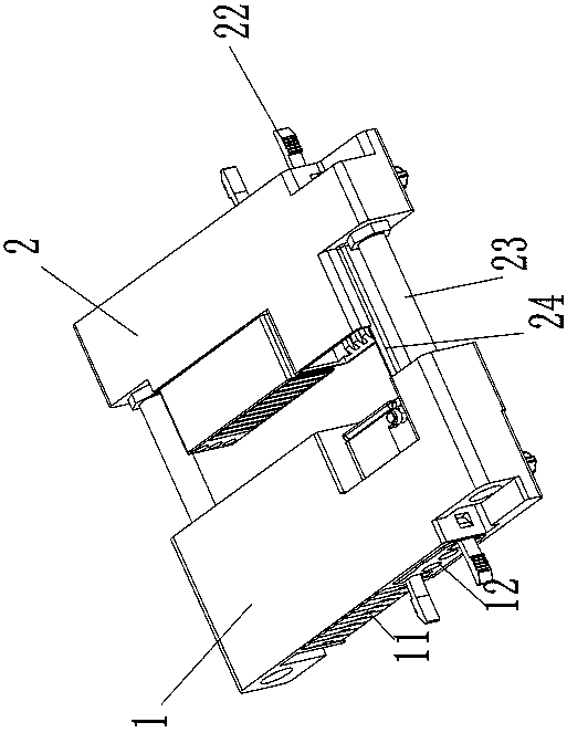
[0037] The specific embodiment of the connector assembly provided by the present invention, such as Figure 1 to Figure 4 described, the connector assembly

[0038] Specifically, it is a photoelectric hybrid connector assembly, including a plug 1 and a socket 2 that are guided to be plugged in. Both the plug 1 and the socket 2 are photoelectric hybrid connectors, that is, they have corresponding electrical modules and optical modules. The optical module on the plug 1 is a pin-type optical module 12, the electrical module on the socket 2 is a jack-type electrical module 21, and the optical module on the socket 2 is a jack-type optical module 22. When the plug 1 and the socket 2 are plugged together, the pin-type electrical module 11 and the jack-type electrical module 21 are plugged correspondingly to transmit electri...


PUM


Abstract

A photoelectric hybrid connector and a connector assembly are provided; the photoelectric hybrid connector includes a connector housing, An optical module mounting position and an electrical module mounting position are independently arranged on the connector housing, an electrical module which enables the connector to have an electrical signal transmission function is detachably mounted on the electrical module mounting position, and an optical module which enables the connector to have an optical signal transmission function is detachably mounted on the optical module mounting position. An electrical module is removably mounted on the mounting position of the electrical module to enable the connector to have an electrical signal transmission function, The optical module can be detachablymounted on the mounting position of the optical module to enable the connector to have the optical signal transmission function, and the corresponding electrical module and / or the optical module canbe selected according to the actual conditions when the optical module is specifically assembled, so as to effectively expand the application site of the optical-electronic hybrid connector and improve the general performance. As the electrical modules and optical modules are independent of each other, each module can be used independently to ensure the independent transmission of the corresponding signal.

Description

technical field [0001] The invention relates to an optical hybrid connector and a connector assembly. Background technique [0002] The existing photoelectric hybrid connector basically integrates the optical contact and the electrical contact directly into one module, such as the flange type photoelectric hybrid connector disclosed in the Chinese utility model patent with the authorized announcement number CN205900870U, including the shell, Corresponding optical contacts and electrical contacts are directly integrated and installed in the shell through the insulator structure, so as to transmit optical signals and electrical signals synchronously when plugged with corresponding adapter connectors. The photoelectric hybrid connector disclosed in the Chinese utility model patent whose authorized announcement number is CN201852962U also has this type of structure. [0003] The above-mentioned photoelectric hybrid connector has a higher degree of integration, is more convenien...

Claims


Application Information

Patent Timeline
Patent Type & Authority Applications(China)
IPC IPC(8): H01R13/42H01R13/514G02B6/38
CPCG02B6/38H01R13/42H01R13/514
Inventor 田建伟石晓强郑伟涛武学顺
Owner CHINA AVIATION OPTICAL-ELECTRICAL TECH CO LTD
Learn More