Pipe bundling and bagging machine

A technology of bagging machine and bundling mechanism, which is applied to the parts of bundling machinery, packaging/bundling items, external support, etc., can solve the problems of slow development, low efficiency and long packaging time of pipe packaging technology.

Active Publication Date: 2019-01-15
佛山市联澜自动化科技有限公司
View PDF4 Cites 9 Cited by
  • Summary
  • Abstract
  • Description
  • Claims
  • Application Information

AI Technical Summary

Problems solved by technology

[0002] The domestic pipe packaging technology is developing slowly. The finishing, bundling and bagging process of the pipe requires the cooperation of multiple equipment and multiple operators. The packaging time is long and the efficiency is low, which has certain limitations.

Method used


Image

  • Pipe bundling and bagging machine
  • Pipe bundling and bagging machine
  • Pipe bundling and bagging machine

Examples


Embodiment Construction

[0158] The present invention will be further described below with reference to the accompanying drawings and embodiments.

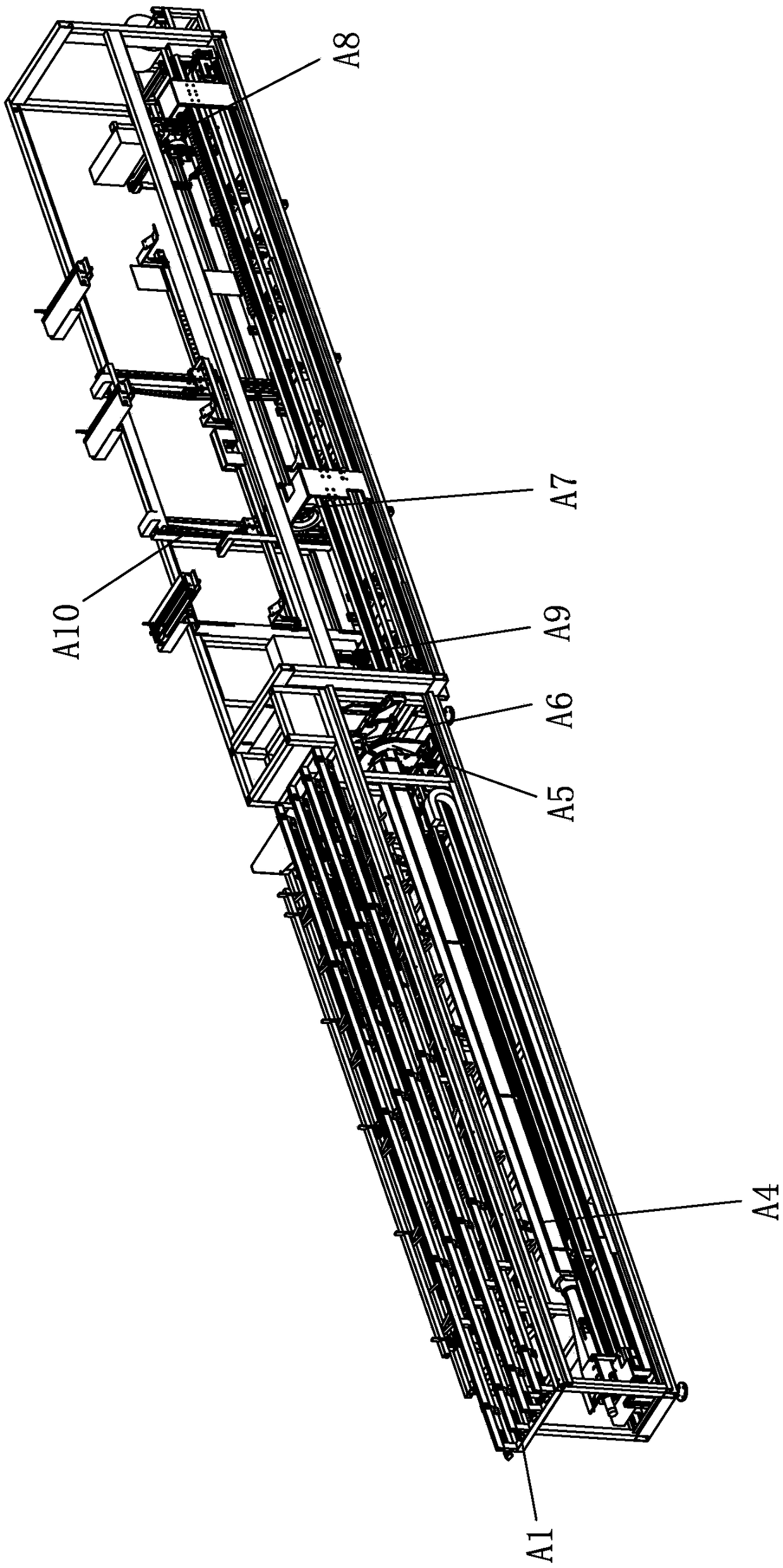
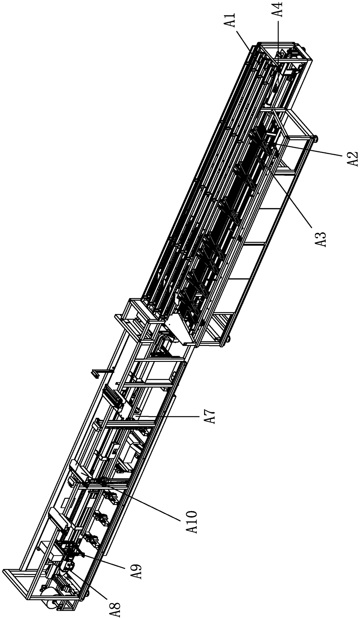
[0159] see Figure 1-Figure 53 , the pipe binding and bagging machine includes a main frame, a turning structure A1, a material guiding device A2, a material pushing device A4, a film binding mechanism, a bagging and packaging mechanism and an unloading device A10 all arranged on the main frame;

[0160] The material turning structure A1 is set above the material guiding device A2, the material pushing device A4, the film binding mechanism and the bagging and packaging mechanism are arranged in sequence from left to right, the material guiding device A2 is located on the side of the material pushing device A4, and the unloading device A10 is located on the side of the material pushing device A4. the sides of the bagging mechanism;

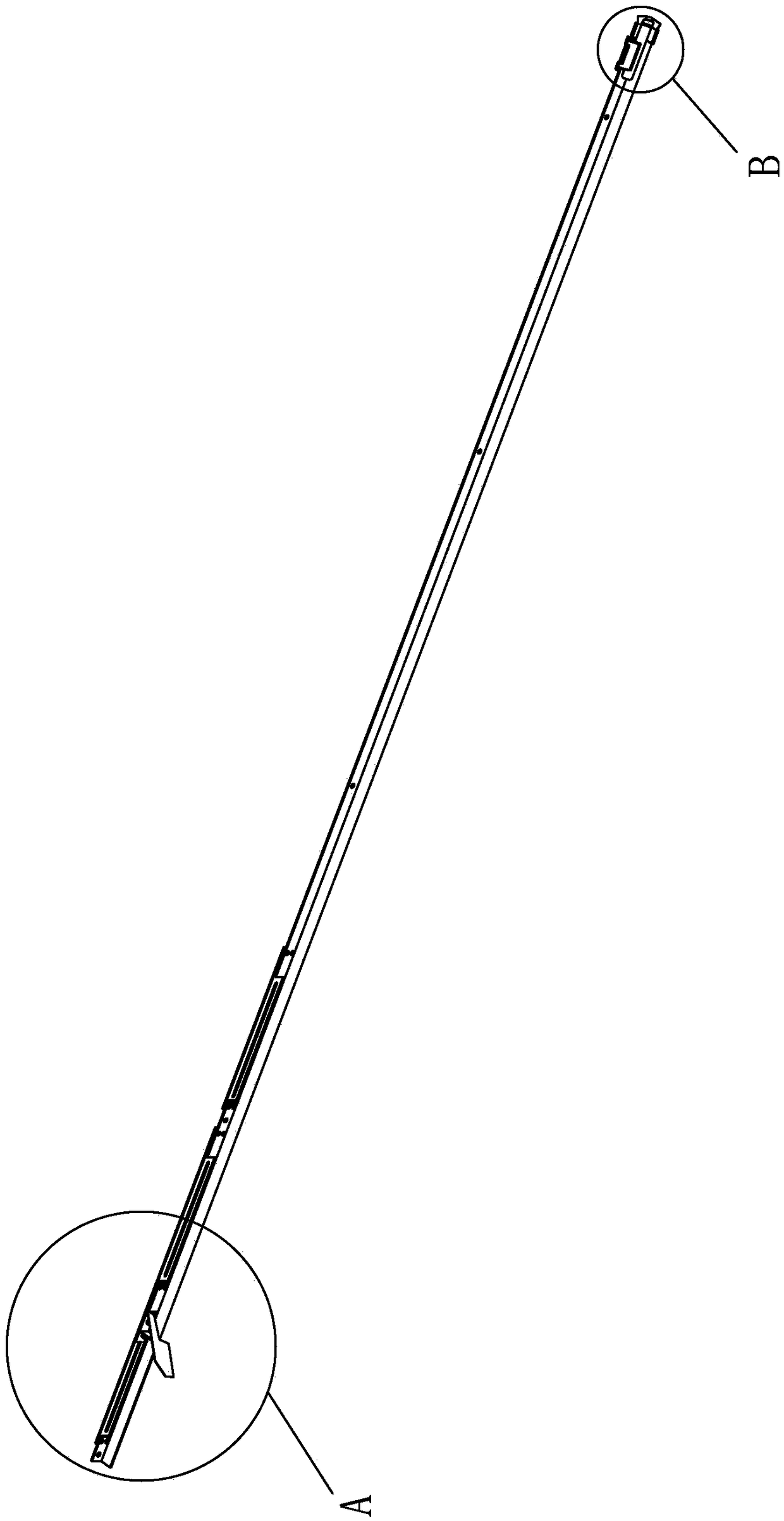
[0161] The material turning structure A1 is used to introduce the external pipe material 90 to be bundled into the bag and ...


PUM


Abstract

The invention provides a pipe bundling and bagging machine, which comprises a main frame. A material turning structure, a material guiding device, a material pushing device, a film binding mechanism,a bagging and packaging mechanism and a discharging device are arranged on the main frame. The material turning structure is arranged above the material guiding device. The material pushing device, the film binding mechanism and the bagging and packaging mechanism are sequentially arranged from left to right. The material guiding device is located on the side part of the pushing device. The discharging device is located on the side part of the bagging and packaging mechanism. The material turning structure is used for introducing the pipe of an external to-be-bundled sleeve bag and turning thepipe into the material guiding device. The material guiding device is used for guiding the pipe to enter the material pushing device. The material pushing device is used for pushing the pipe to the film binding mechanism for film binding, and then the bagging is carried out in the bagging and packaging mechanism. The discharging device is used for taking out the pipe out of the film binding mechanism after the bagging operation. According to the pipe binding and bagging machine, the continuous operation of arranging, binding and bagging the pipes is achieved.

Description

technical field [0001] The invention relates to a pipe binding bagging machine. Background technique [0002] The domestic pipe packaging technology is developing slowly. The finishing, bundling and bagging process of the pipe requires the cooperation of multiple equipment and multiple operators. The packaging time is long and the efficiency is low, which has certain limitations. Contents of the invention [0003] The purpose of the present invention is to overcome the shortcomings of the above-mentioned prior art, and provide a pipe bundling and bagging machine to realize the coherent operation of pipe arrangement, bundling and bagging. [0004] The purpose of the present invention is achieved like this: [0005] A pipe bundling and bagging machine, comprising a main frame, a material turning structure all arranged on the main frame, a material guiding device, a material pushing device, a film binding mechanism, a bagging and packaging mechanism, and a material unloading...

Claims


Application Information

Patent Timeline
IPC IPC(8): B65B27/10B65B13/18B65B11/02B65B5/08B65B61/00B65B43/54B65B51/10B65B61/06
CPCB65B5/08B65B11/02B65B13/18B65B27/10B65B43/54B65B51/10B65B61/00B65B61/06
Inventor 李燕利
Owner 佛山市联澜自动化科技有限公司
Why Eureka
Try Eureka