


Quick Research
Generate reliable direction feasibility study reports for your R&D in just a few steps.

Technical Q&A
Discover and master advanced knowledge NOW. Basics, ideas, possibilities, all at once.

Find Solutions
As an expert in R&D theories, this can generate solutions to your technical problems instantly.

Evaluate Feasibility
Analyze your overall solution with one click, know your potential R&D risks in advance.

Monitor Landscape
Get weekly tech updates, stay abreast of the latest tech innovations and key insights.
A high-efficiency reactor for accelerating heat dissipation
A technology of heat dissipation rate and reaction kettle, applied in chemical/physical/physical-chemical stationary reactors, chemical/physical/physical-chemical processes, chemical instruments and methods, etc., can solve the problem of high cost
- Summary
- Abstract
- Description
- Claims
- Application Information
AI Technical Summary
Problems solved by technology
Method used
Image

Examples
Embodiment 1
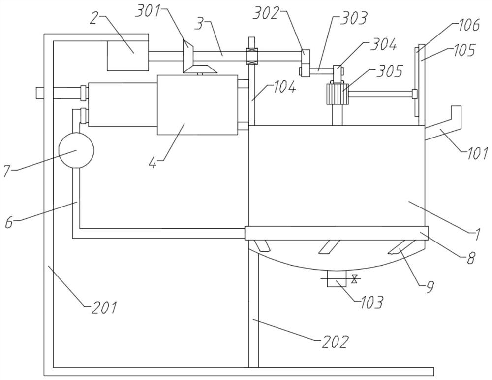
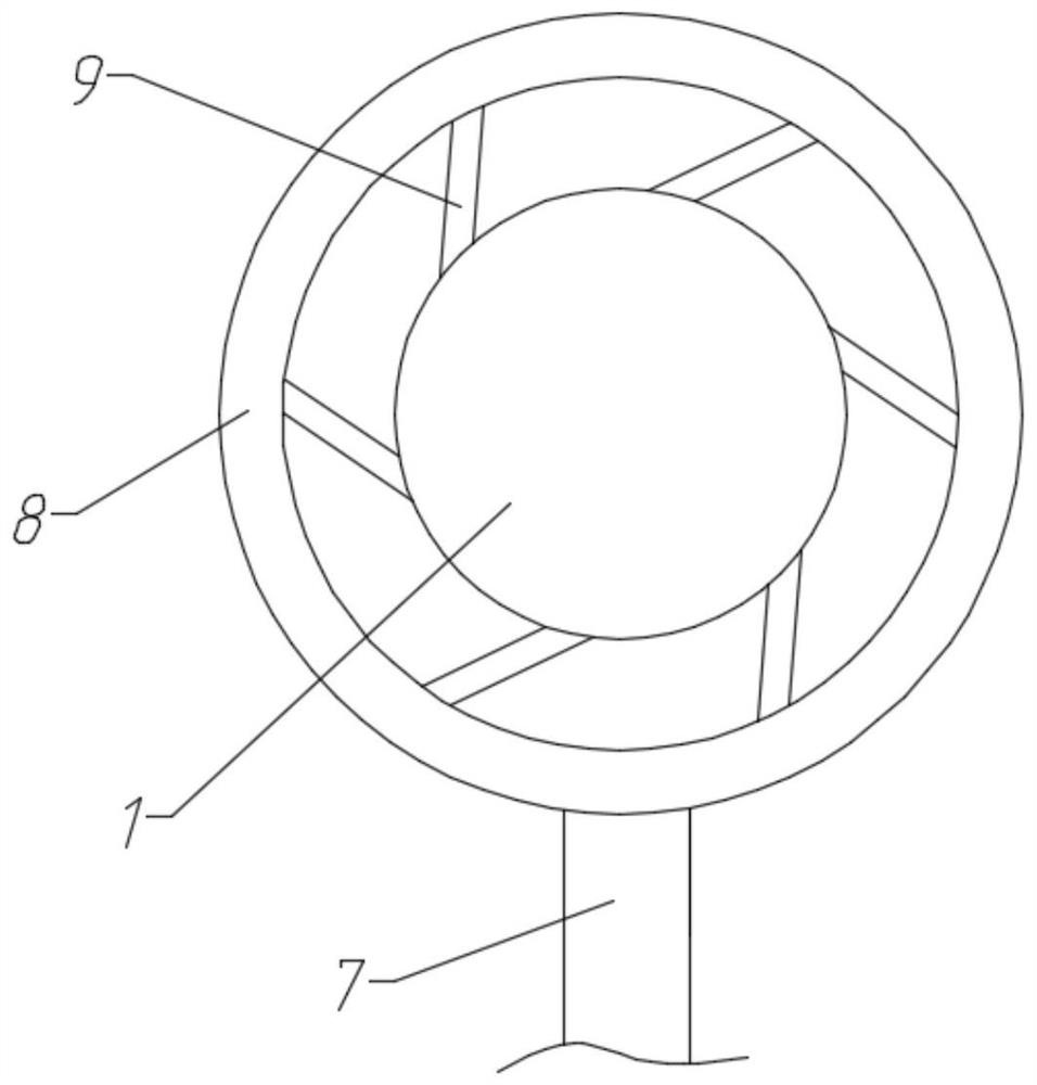
[0041] A high-efficiency reaction kettle for accelerating heat dissipation, including a tank body 1, a mounting frame 201, a lifting component and a suction structure 4;
[0042] The mounting frame 201 is a similar C-shaped plate bent up and down, and the upper end is bent shorter than the lower end; the tank body 1 is arranged on the left side of the mounting frame 201, and the left end of the bottom of the tank body 1 is fixedly connected to the lower end of the mounting frame 201 through a support rod 202; The drive motor 2 is installed on the upper end of the frame 201, and the output end of the drive motor 2 stretches out horizontally to the right and is connected with the driving shaft 3, which is arranged higher than the tank body 1;
[0043] A liquid inlet pipe 101 is connected to the top of one side of the tank body 1; a vertical left support plate 104 and a right support plate 105 are fixedly connected to the left and right ends of the top of the tank body 1; The rig...
Embodiment 2
[0054] A high-efficiency reaction kettle for accelerating heat dissipation, including a tank body 1, a mounting frame 201, a lifting component and a suction structure 4;
[0055] The mounting frame 201 is a similar C-shaped plate bent up and down, and the upper end is bent shorter than the lower end; the tank body 1 is arranged on the left side of the mounting frame 201, and the left end of the bottom of the tank body 1 is fixedly connected to the lower end of the mounting frame 201 through a support rod 202; The drive motor 2 is installed on the upper end of the frame 201, and the output end of the drive motor 2 stretches out horizontally to the right and is connected with the driving shaft 3, which is arranged higher than the tank body 1;
[0056] A liquid inlet pipe 101 is connected to the top of one side of the tank body 1; a vertical left support plate 104 and a right support plate 105 are fixedly connected to the left and right ends of the top of the tank body 1; The rig...
Embodiment 3
[0065] A high-efficiency reaction kettle for accelerating heat dissipation, including a tank body 1, a mounting frame 201, a lifting component and a suction structure 4;
[0066] The mounting frame 201 is a similar C-shaped plate bent up and down, and the upper end is bent shorter than the lower end; the tank body 1 is arranged on the left side of the mounting frame 201, and the left end of the bottom of the tank body 1 is fixedly connected to the lower end of the mounting frame 201 through a support rod 202; The drive motor 2 is installed on the upper end of the frame 201, and the output end of the drive motor 2 stretches out horizontally to the right and is connected with the driving shaft 3, which is arranged higher than the tank body 1;
[0067] A liquid inlet pipe 101 is connected to the top of one side of the tank body 1; a vertical left support plate 104 and a right support plate 105 are fixedly connected to the left and right ends of the top of the tank body 1; The rig...
PUM
 Abstract
Description
Claims
Application Information
 - R&D Engineer
- R&D Manager
- IP Professional
- Industry Leading Data Capabilities
- Powerful AI technology
- Patent DNA Extraction
Browse by: Latest US Patents, China's latest patents, Technical Efficacy Thesaurus, Application Domain, Technology Topic, Popular Technical Reports.
© 2024 PatSnap. All rights reserved.Legal|Privacy policy|Modern Slavery Act Transparency Statement|Sitemap|About US| Contact US: help@patsnap.com