
Door locking mechanism

A door lock and door body technology, applied in the direction of power control mechanism, wing leaf control mechanism, building lock, etc., can solve the problem of theft

Inactive Publication Date: 2019-01-11
汪贤荣
View PDF0 Cites 4 Cited by
  • Summary
  • Abstract
  • Description
  • Claims
  • Application Information

AI Technical Summary

Problems solved by technology

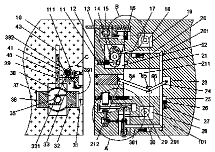
[0002] All kinds of doors are involved in life, and they generally have access control devices, but traditional access control devices generally need to be manually closed to make the door automatically locked. If people forget to lock the door, there will be stolen Risk, most of the time people want the door to be able to lock itself without manual locking, so this invention designs a door that can lock itself

Method used


Image

  • Door locking mechanism
  • Door locking mechanism
  • Door locking mechanism

Examples


Embodiment Construction

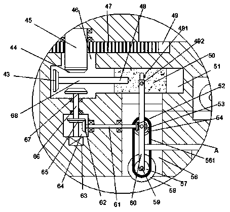
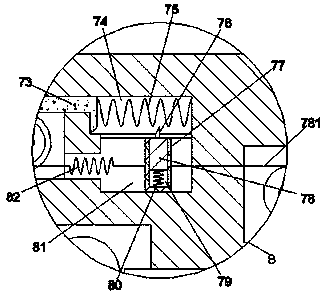
[0015] Combine below Figure 1-5 The present invention will be described in detail.

[0016] refer to Figure 1-5 , a door locking mechanism according to an embodiment of the present invention includes a wall body 10 and a door body 101, the wall body 10 is provided with a first cavity 37, and the left and right end surfaces of the first cavity 37 are symmetrically opened There is a first groove 36, and a first slider 32 is slid in the first groove 36, and a first rack 33 arranged symmetrically up and down is fixed on the end surface of the side of the first slider 32 close to each other , the first gear 35 is meshedly connected between the first racks 33, the first gear 35 is rotatably arranged on the rear wall of the first cavity 37, and the first slider 32 is fixed between There is a vertically symmetrical elastic plate 38, the bottom end wall of the first cavity 37 is provided with a first chute 42 extending upward, and the top end surface of the elastic plate 38 at the ...


PUM


Abstract

The invention discloses a door locking mechanism. The door locking mechanism comprises a wall body and a door body; the wall body is internally provided with a first cavity; first grooves are symmetrically formed in the left end face and the right end face of the first cavity; first sliding blocks are slidably arranged in the first grooves; first racks arranged symmetrically up and down are fixedly arranged on the end faces of the sides, close to each other, of the first sliding blocks; a first gear is connected between the first racks in an engaged mode; the first gear is rotationally arranged on the rear wall of the first cavity; elastic plates arranged symmetrically up and down are fixedly arranged between the first sliding blocks; the end wall of the bottom of the first cavity is provided with a first sliding groove extending upwards; a first sliding plate extending upwards is fixedly arranged on the end surface of the top of the elastic plate located at the top; and the first sliding plate is slidably arranged in the first sliding groove.

Description

technical field [0001] The invention relates to the technical field of access control, in particular to a door locking mechanism. Background technique [0002] All kinds of doors are involved in life, and they generally have access control devices, but traditional access control devices generally need to be manually closed to make the door automatically locked. If people forget to lock the door, there will be stolen Risk, most of the time people want the door to be able to lock itself without manual locking, so the present invention designs a door that can lock itself. Contents of the invention [0003] The object of the present invention is to provide a door locking mechanism for overcoming the above-mentioned defects in the prior art. [0004] A door locking mechanism according to the present invention includes a wall body and a door body, the wall body is provided with a first cavity, the left and right end surfaces of the first cavity are symmetrically opened with fir...

Claims


Application Information

Patent Timeline
IPC IPC(8): E05F15/643E05C9/00E05B65/08
CPCE05F15/643E05B65/08E05C9/00
Inventor 汪贤荣
Owner 汪贤荣
Learn More