Waste compression treatment device

A technology for compressing and processing waste, applied in the field of machinery, can solve the problems of waste liquid cleaning, cost, economic benefit, lack of manual waste compressing processor, etc. maintain a stable effect

Inactive Publication Date: 2019-01-11
YULIN UNIV
View PDF9 Cites 0 Cited by
  • Summary
  • Abstract
  • Description
  • Claims
  • Application Information

AI Technical Summary

Problems solved by technology

[0003] Although the compression of municipal domestic waste has been applied in daily life, there is still a lack of manual waste compactors
The following problems exist in the design of waste manual compression processors: energy consumption, floor area, waste liquid cleaning, cost, economic benefits, etc.

Method used


Image

  • Waste compression treatment device
  • Waste compression treatment device

Examples


Embodiment 1

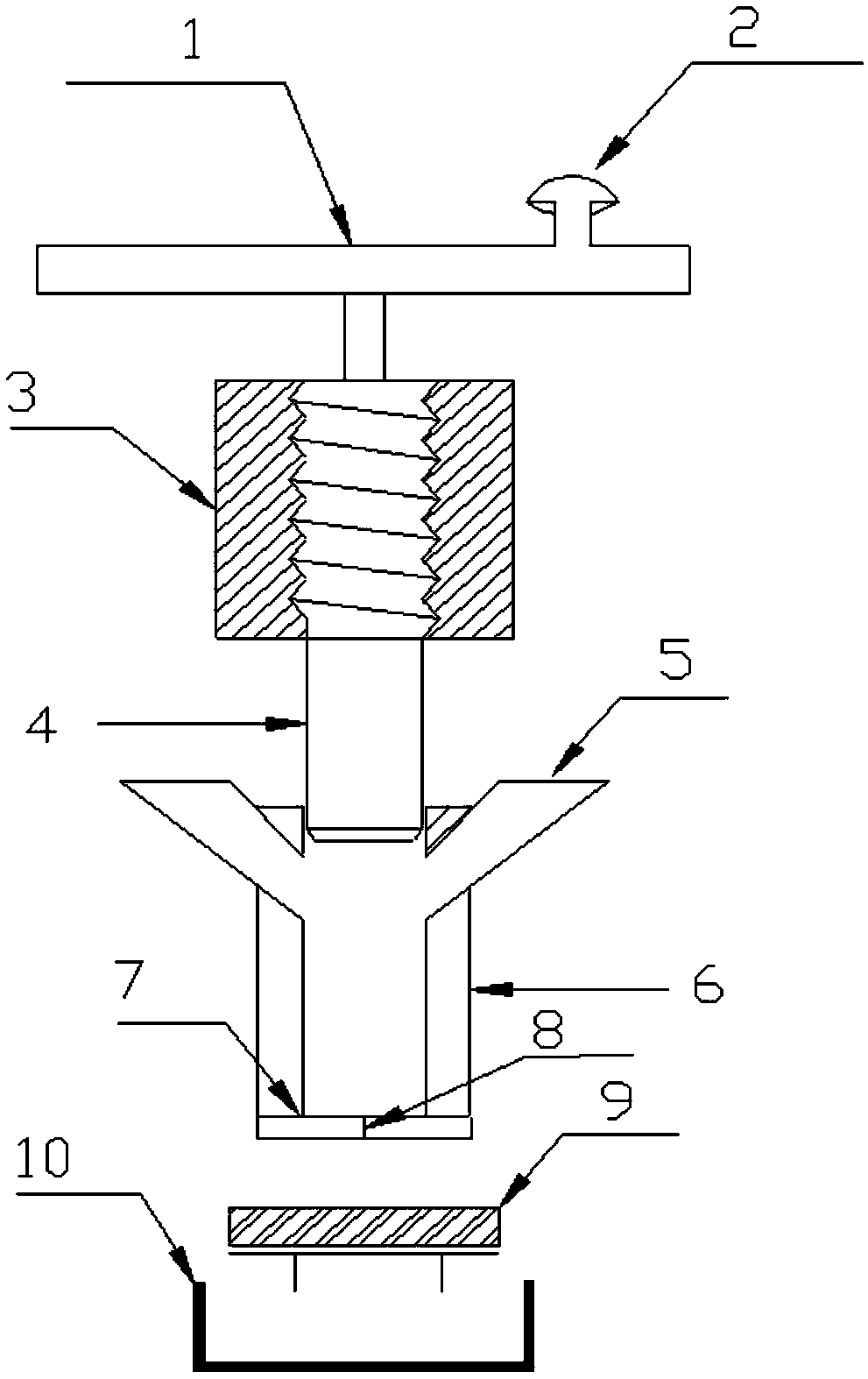
[0024] see figure 1 , the present invention includes a frame 3, the frame 3 is provided with a shaft 4, the shaft 4 is provided with an external thread, the frame 3 is provided with an internal thread that cooperates with the external thread, and the top surface of the shaft 4 is connected with a turntable 1, The top of the turntable 1 is provided with a crank 2, the lower part of the frame 3 is provided with a compression chamber 6, the shaft 4 can extend into the compression chamber 6, the axial surface of the shaft 4 is attached to the inner surface of the compression chamber 6, and the side of the compression chamber 6 is provided with The waste input port 5 and the bottom of the compression chamber 6 are provided with a waste outlet 7. When collecting waste, the shaft 4 is placed on the top of the compression chamber 6; A liquid hole, a waste liquid collector 10 is arranged below the waste outlet 7 and a filter packaging device 9 is provided below the filter packaging dev...

Embodiment 2

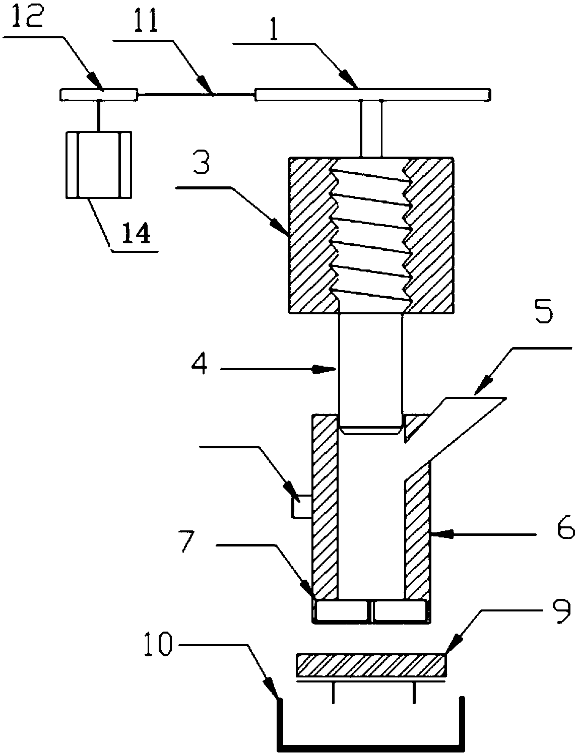
[0028] see figure 2 , the present invention comprises a frame 3, the frame 3 is provided with a shaft 4, the shaft 4 is provided with an external thread, the frame 3 is provided with an internal thread that cooperates with the external thread, and the bottom of the frame 3 is provided with a compression chamber 6, The shaft 4 can extend into the compression chamber 6, and the axial surface of the shaft 4 is attached to the inner surface of the compression chamber 6. The side of the compression chamber 6 is provided with a waste input port 5, and the bottom of the compression chamber 6 is provided with a waste outlet 7. When collecting waste, the shaft 4 is placed on the top of the compression chamber 6; when the waste is compressed, the shaft 4 can be in contact with the waste outlet 7, and a number of seepage holes begin to appear on the waste outlet 7, and a filter packing device 9 is provided below the waste outlet 7. The waste liquid collector 10, the top surface of the s...


PUM


Abstract

The invention discloses a waste compression treatment device. According to the waste compression treatment device, a shaft is rotated to be extended into a compression chamber, waste in the compression chamber is compressed, and compressed waste is discharged from a waste outlet. Because sliding is replaced by rolling through threaded connection, friction and energy consumption are reduced, the transmission ratio is kept stable, the mechanical efficiency is high, and the waste compression treatment device is simple and compact in structure, easy to popularize and use, small in occupied area, flexible and free to move, and not limited by use occasions.

Description

technical field [0001] The invention belongs to the field of machinery, and in particular relates to a waste compression treatment device. Background technique [0002] With the development of national network technology and big data, people's living standards have been greatly improved, people's consumption concepts have also undergone tremendous changes, and the consumption index is also rising. In the past, people went shopping, but now people's lifestyles and consumption patterns have undergone great changes, especially the lifestyles of young people are completely different from before: online shopping, group purchases, and even food need to be ordered online, which brings people a convenience life. People enjoy the convenience brought by the rapid economic development, but also pay more and more attention to the pollution of urban domestic waste. The composition of urban domestic waste has also changed: express plastic bags, cartons, mineral water bottles, etc., show...

Claims


Application Information

Patent Timeline
Patent Type & Authority Applications(China)
IPC IPC(8): B30B9/04B30B9/30
CPCB30B9/04B30B9/30
Inventor 李瑞瑞王战辉闫皓钞锐张恒曹鹏程刘田雨陈乐丹
Owner YULIN UNIV
Why Eureka
Try Eureka