Liquid light hydrocarbon gasification system

A gasification system, light hydrocarbon technology, applied in chemical instruments and methods, chemical/physical processes, liquid fuel supply/distribution, etc., can solve the problems of low gasification efficiency, energy waste, affecting pipeline safety, etc. Improve safety and stability, improve mixing effect, and promote the effect of uniform mixing

Inactive Publication Date: 2019-01-08
武汉润同和新能源科技发展有限公司 +1
View PDF5 Cites 0 Cited by
  • Summary
  • Abstract
  • Description
  • Claims
  • Application Information

AI Technical Summary

Problems solved by technology

[0002] When liquid light hydrocarbons (such as pentane) are used as fuel, it is necessary to gasify the liquid light hydrocarbons and air, and then transport them to users for use. However, the existing liquefied gas equipment usually only has a single pipeline, and valves are installed on the pipeline To control the opening and closing or flow rate of the pipeline, the gasification efficiency of the equipment is not high, and some liquid light hydrocarbons are easily mixed in the pipeline that transports the gas to the user, which causes energy waste and affects pipeline safety
In addition, the gasification of liquid light hydrocarbons requires a gasifier. The existing gasifier is usually only a container filled with air, and liquid light hydrocarbons are passed into the container to realize the gasification of light hydrocarbons. This gasification device Although the structure is simple, the gasification efficiency is low, and the mixture of light hydrocarbons and air is not completely uniform

Method used


Image

  • Liquid light hydrocarbon gasification system
  • Liquid light hydrocarbon gasification system
  • Liquid light hydrocarbon gasification system

Examples


Embodiment Construction

[0024] Embodiments of the present invention are described in detail below, examples of which are shown in the drawings, wherein the same or similar reference numerals designate the same or similar elements or elements having the same or similar functions throughout. The embodiments described below by referring to the figures are exemplary only for explaining the present invention and should not be construed as limiting the present invention.

[0025] In describing the present invention, it is to be understood that the terms "center", "upper", "lower", "front", "rear", "left", "right", "vertical", "horizontal", The orientations or positional relationships indicated by "top", "bottom", "inner", "outer", etc. are based on the orientations or positional relationships shown in the drawings, and are only for the convenience of describing the present invention and simplifying the description, rather than indicating or implying the It should not be construed as limiting the invention ...


PUM


Abstract

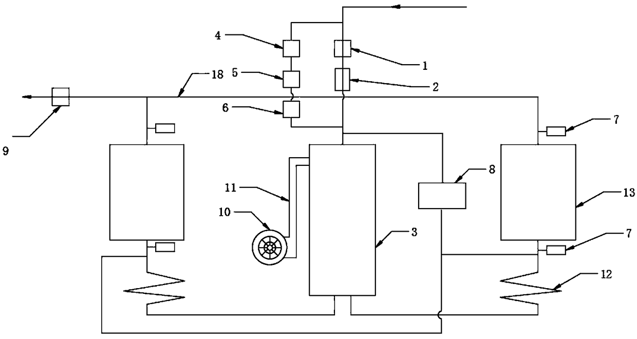
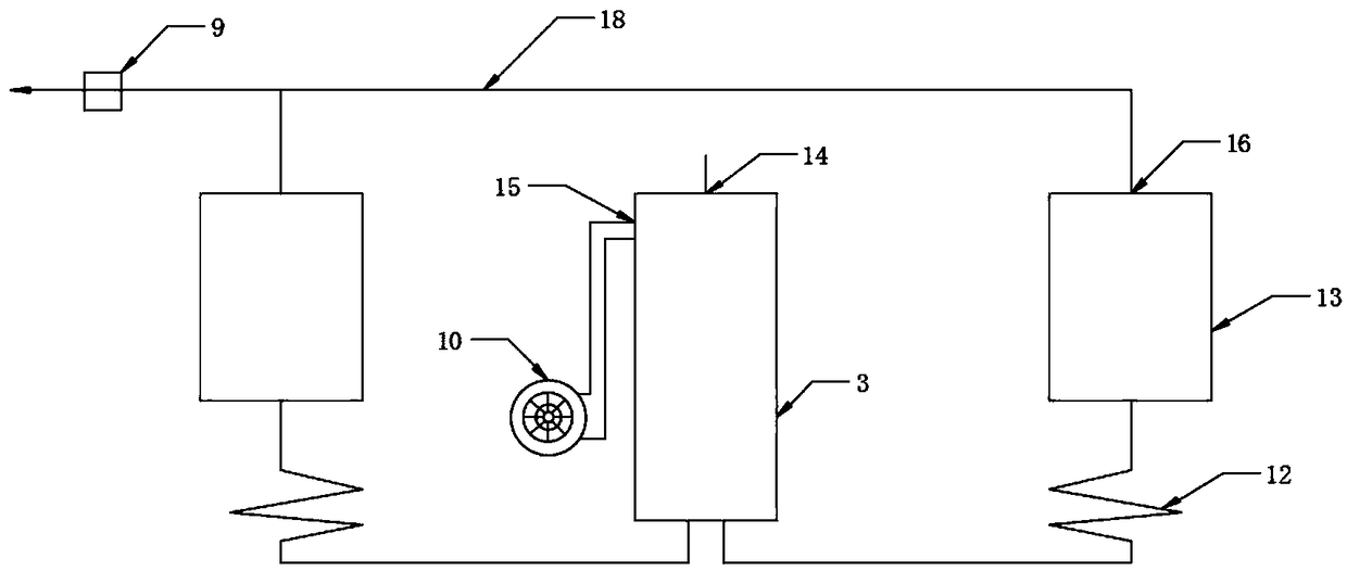
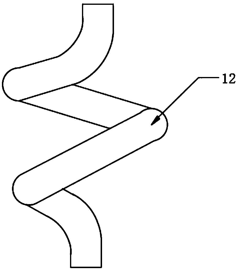
The invention discloses a liquid light hydrocarbon gasification system. The liquid light hydrocarbon gasification system comprises a gasification pipeline, an auxiliary starting pipeline, a detectionpipeline, a jet flow mixing tank, a cyclone spiral tube and a distributor; the upper end of the jet flow mixing tank is provided with a liquid light hydrocarbon inlet and an air inlet; the lower end of the jet flow mixing tank communicates with one end of the cyclone spiral tube, the other end of the cyclone spiral tube communicates with one end of the distributor, and the other end of the distributor is provided with an air outlet; the gasification pipeline is sequentially connected with a first electromagnetic valve and a proportional regulating valve from the inlet end to the outlet end ofthe gasification pipeline; the auxiliary starting pipeline is sequentially connected with a second electromagnetic valve, a manual adjusting valve and a time relay from the inlet end to the outlet endof the auxiliary starting pipeline; and the detection pipeline comprises a safety probe and an oil return pump. According to the liquid light hydrocarbon gasification system, under the action of thejet flow mixing tank, air can be fully contacted and mixed with liquid light hydrocarbon; and gas mixed in the jet flow mixing tank can further promote mixture between the light hydrocarbons and the air and improves the mixing effect through the cyclone flow guiding function of the cyclone spiral tube.

Description

technical field [0001] The invention relates to the technical field of liquefied gas gasification equipment, in particular to a liquid light hydrocarbon gasification system. Background technique [0002] When liquid light hydrocarbons (such as pentane) are used as fuels, it is necessary to gasify liquid light hydrocarbons and air, and then transport them to users for use. However, existing liquefied gas equipment usually only has a single pipeline, and valves are installed on the pipeline Controlling the opening and closing or flow rate of the pipeline, the gasification efficiency of the equipment is not high, and some liquid light hydrocarbons are easily mixed in the pipeline that transports the gas to the user, which causes energy waste and affects pipeline safety. In addition, the gasification of liquid light hydrocarbons requires a gasifier. The existing gasifier is usually only a container filled with air, and liquid light hydrocarbons are passed into the container to r...

Claims


Application Information

Patent Timeline
Patent Type & Authority Applications(China)
IPC IPC(8): F23K5/22B01F3/02B01F23/10
CPCF23K5/22B01F23/10
Inventor 周春和何建国韩先斌杨元庆
Owner 武汉润同和新能源科技发展有限公司
Why Eureka
Try Eureka