Transfer structure
A technology for transferring structures and transferring parts, applied in metal processing, assembling machines, metal processing equipment, etc., can solve the problems of dislocation of at least two parts, improper installation of the assembly, etc., and achieve the effect of increasing the scope of use
- Summary
- Abstract
- Description
- Claims
- Application Information
AI Technical Summary
Problems solved by technology
Method used
Image

Examples
Embodiment 1
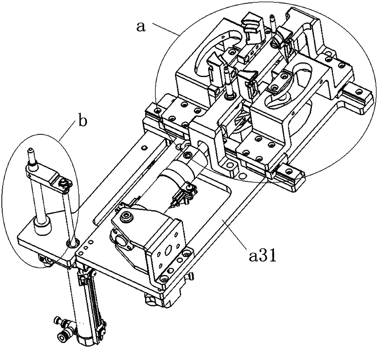
[0054] This embodiment provides a transfer structure, such as Figure 1 to Figure 12 As shown, the transfer structure includes a base a31, a clamping mechanism a and a limiting mechanism b arranged side by side on the base a31.
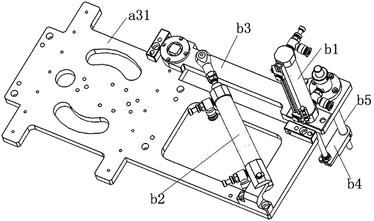
[0055] Such as figure 2 and Figure 5 As shown, the limit mechanism b includes a first driver b1, a second driver b2, a first transition plate b3, a second transition plate b4, and a limit member b5. Wherein, one end of the first transition plate b3 is hinged on the base a31, and the other end is suspended in the air; the second driver b2 can be selected as a second air cylinder, and the telescopic shaft of the second air cylinder is connected to the first transition plate b3.
[0056] The first driver b1 and the limiter b5 are fixed side by side on the first transition plate b3, the first driver b1 can be selected as the first cylinder, the telescopic shaft of the first cylinder is fixed on the second transition plate b4, and the limiter b5 The o...
Embodiment 2
[0091] This embodiment provides a transfer structure, compared with the transfer structure provided in Embodiment 1, the difference lies in:
[0092] In the clamping mechanism in this embodiment, the spring plunger can be replaced by a spring, or other existing elastic supports a16, and the number of elastic supports a16 can be one, two, three, four, etc., The specific number of settings depends on actual needs. Alternatively, the elastic supporting member a16 may not be provided, and only the first groove is used to clamp the part to be transferred.
[0093] As a modification, the third clamping part a13 can also be independent of the second clamping part a12, and a first groove recessed from outside to inside is provided on the outer side walls of the first chuck body a1 and the second chuck body a2. The first groove can also be replaced by other structures, such as protrusions, correspondingly, a groove is provided on the wall surface of the inner chamber of the part to be...
Embodiment 3
[0096] This embodiment provides a transfer structure, compared with the transfer structure provided in embodiment 1 or embodiment 2, the difference is that:
[0097] The driving mechanism a3 can be replaced by other driving mechanisms, such as setting the clamping cylinder separately, fixing the first mounting plate a351 and the second mounting plate a352 respectively on the two sliding parts of the clamping cylinder, thereby changing the first clamping head The distance between the body a1 and the second chuck body a2.
[0098] As a modification, only one set of the first chuck body a1 and the second chuck body can be provided. Correspondingly, the above-mentioned first mounting plate a351 and the second mounting plate a352 are not required, and the first chuck body a1 and the second mounting plate a352 are directly connected to each other. The second chuck body a2 is respectively fixed on a slider a34. Alternatively, multiple sets of the first chuck body a1 and the second c...
PUM
 Abstract
Description
Claims
Application Information
 - R&D
- Intellectual Property
- Life Sciences
- Materials
- Tech Scout
- Unparalleled Data Quality
- Higher Quality Content
- 60% Fewer Hallucinations
Browse by: Latest US Patents, China's latest patents, Technical Efficacy Thesaurus, Application Domain, Technology Topic, Popular Technical Reports.
© 2025 PatSnap. All rights reserved.Legal|Privacy policy|Modern Slavery Act Transparency Statement|Sitemap|About US| Contact US: help@patsnap.com