
An optical cable connector

A technology of optical cable joints and connecting plates, which is applied in the direction of optics, light guides, optical components, etc., can solve the problems of easy bending of optical cables, adjustment of joints, and skin cracks, and achieve the effect of ensuring dust prevention

Active Publication Date: 2020-07-14
武汉亿联高清信息科技有限公司
View PDF5 Cites 0 Cited by
  • Summary
  • Abstract
  • Description
  • Claims
  • Application Information

AI Technical Summary

Problems solved by technology

[0003] During the installation process of the optical cable, it is often necessary to combine multiple groups of optical cables together. The current limit measures for the optical cable of the connector are mostly to use the limit ring to fix the entrance and exit of the optical cable to avoid its deviation. The hard limit ring will wear the skin of the optical cable, which will easily cause the skin to break for a long time, and the diameter of the limit ring is limited, which is inconvenient to operate, and multiple screws need to be tightened; the joint cannot be adjusted according to the installation position. Makes the cable easy to bend when fixed

Method used


Image

  • An optical cable connector
  • An optical cable connector
  • An optical cable connector

Examples


Embodiment Construction

[0029] In order to make the technical means, creative features, goals and effects achieved by the present invention easy to understand, the present invention will be further described below in conjunction with specific embodiments.

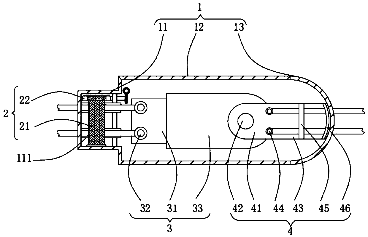
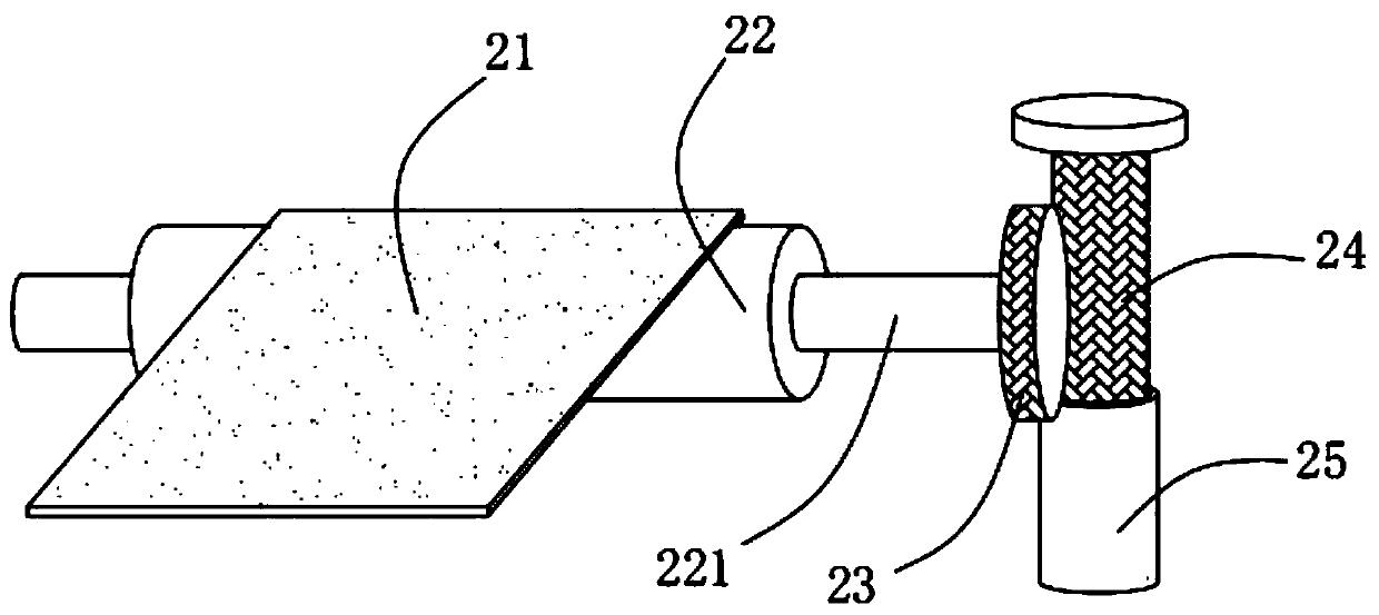
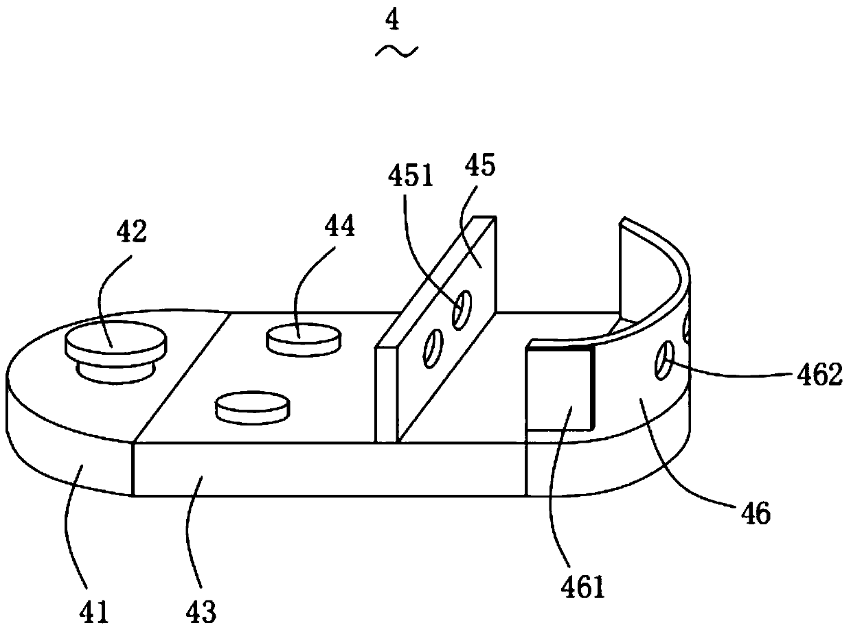
[0030] Such as Figure 1-Figure 7 As shown, an optical cable joint according to the present invention includes a first outer protection mechanism 1, a limit mechanism 2, a first transmission mechanism 3, a second transmission mechanism 4, a shielding mechanism 5 and a second outer protection mechanism 6; The inner end of the first outer protection mechanism 1 is provided with the limiting mechanism 2, and the limiting mechanism 2 is used to limit the optical cable; the limiting mechanism 2 is electrically connected to the first conducting mechanism 3, The first transmission mechanism 3 is rotatably connected to the second transmission mechanism 4, the first transmission mechanism 3 and the second transmission mechanism 4 are used to transmit infor...


PUM


Abstract

The invention relates to the technical field of communication equipment and particularly relates to an optical cable connector. The optical cable connector includes a first outer protection mechanism,a limit mechanism, a first conduction mechanism, a second conduction mechanism, shielding mechanisms and a second outer protection mechanism. During light connection, a screw can be screwed to drivea first winding column to rotate, in turn, the cable is tightly pressed by a limit band to fix the cable, so the cable is firmly and stably arranged in a wiring slot, and the limit need of cables of different diameters can be met; the second conduction mechanism is rotatably connected with the first conduction mechanism, so a third connection board can rotate to different orientations, the steering need in the cable mounting process is met, and bending the cable is not needed; in the rotation adjustment process of a third connection plate, the two shielding mechanisms are driven to follow themovement, so a flow slot only have an opening in the area where the wiring slot is located, other areas are blocked by protection tapes, and the dust and water resistant effect is guaranteed.

Description

technical field [0001] The invention relates to the technical field of communication equipment, in particular to an optical cable connector. Background technique [0002] Optical cables are manufactured to meet optical, mechanical or environmental performance specifications. It is a communication cable assembly that uses one or more optical fibers placed in a sheath as a transmission medium and can be used individually or in groups. [0003] During the installation process of the optical cable, it is often necessary to combine multiple groups of optical cables together. The current limit measures for the optical cable of the connector are mostly to use the limit ring to fix the entrance and exit of the optical cable to avoid its deviation. The hard limit ring will wear the skin of the optical cable, which will easily cause the skin to break for a long time, and the diameter of the limit ring is limited, which is inconvenient to operate, and multiple screws need to be tighten...

Claims


Application Information

Patent Timeline
Patent Type & Authority Patents(China)
IPC IPC(8): G02B6/44
CPCG02B6/4439
Inventor 胡林斌吴国良
Owner 武汉亿联高清信息科技有限公司
Learn More