
Working indicator

A working indicator light and lampshade technology, which is applied to lighting devices, fixed lighting devices, lighting applications, etc., can solve the problems of inconvenient production, complicated operation, waste of resources, etc., and achieve the effects of convenient installation, simple disassembly, and cost saving.

Inactive Publication Date: 2019-01-04
SHANGHAI UPUN IND CONTROL SYST
View PDF5 Cites 0 Cited by
  • Summary
  • Abstract
  • Description
  • Claims
  • Application Information

AI Technical Summary

Problems solved by technology

If any part in the lamp housing is damaged, the working indicator light needs to be replaced as a whole, which causes waste of resources and increases the cost. While replacing the working indicator light, it is necessary to suspend the operation of the equipment, which is complicated to operate and brings inconvenience to production.

Method used


Image

  • Working indicator
  • Working indicator
  • Working indicator

Examples


Embodiment Construction

[0032] The present invention will be further described in detail below in conjunction with the accompanying drawings and embodiments. It should be understood that the specific implementation manners described here are only used to explain the present invention, rather than to limit the present invention. In addition, it should be noted that, for the convenience of description, only some structures related to the present invention are shown in the drawings but not all structures.

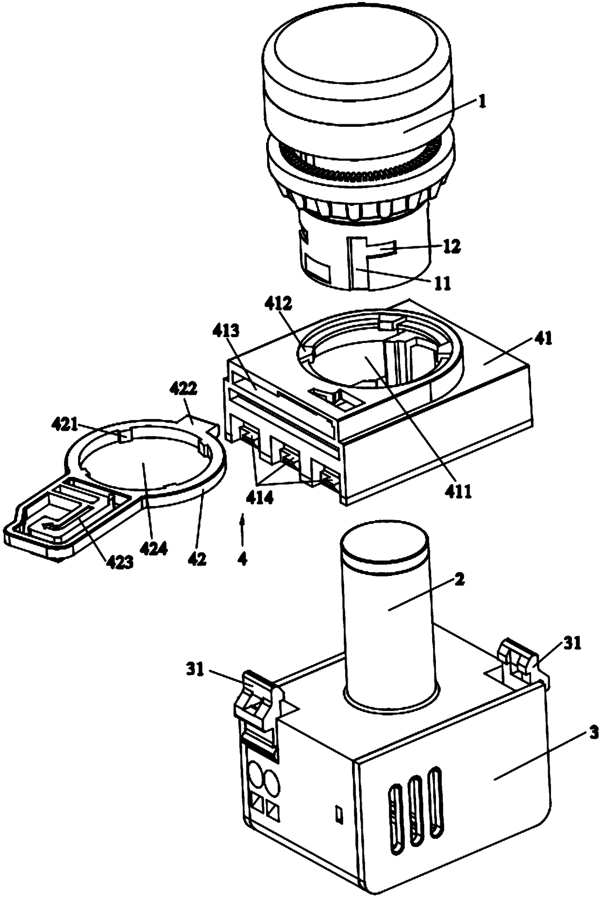
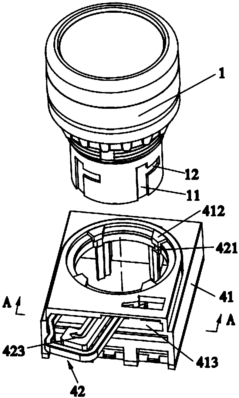
[0033] Such as figure 1 As shown, this embodiment provides a working indicator light, which includes a lampshade 1, a light-emitting part 2, a lamp holder 3 and a limit assembly 4, the light-emitting part 2 is installed on the lamp holder 3, and the limit assembly 4 includes a middle The seat 41 and the dial ring 42, the middle seat 41 is provided with a first through hole 411, the dial ring 42 is positioned at the axial upper limit of the first through hole 411, the first through hole 411 accommoda...


PUM


Abstract

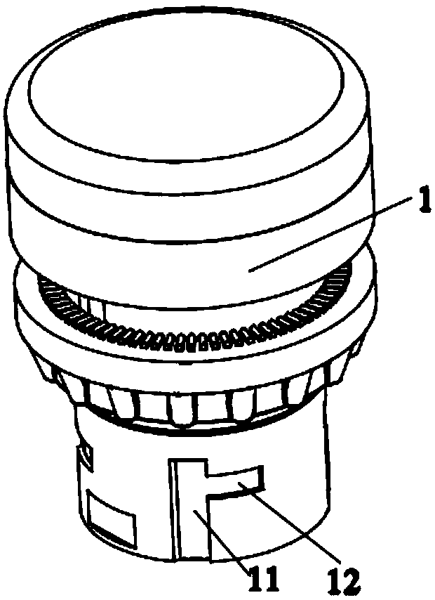
The invention relates to the technical field of light indication and discloses a working indicator. The working indicator comprises a light shade, a light emitting component, a light holder and a limiting assembly, wherein the limiting assembly comprises a middle base and a shifting and clamping ring, the middle base is clamped on the light holder, a first through hole is arranged in the middle base, the light emitting component is accommodated in the first through hole, and a first clamping projection is arranged on the inner wall of the first through hole; the shifting and clamping ring carries out limiting in the axial direction of the first through hole and is provided with a second clamping projection vertically coincided with the first clamping projection, and the shifting and clamping ring can rotate in the axial direction so as to enable the first clamping projection to be vertically coincided with or staggered with the second clamping projection; the light shade is arranged inthe first through hole and covers the light emitting component, the light shade is provided with a vertical clamping groove and a transverse clamping groove, and when the first clamping projection and the second clamping projection are vertically coincided, both the first clamping projection and the second clamping projection can slide in the vertical clamping groove; and when the first clampingprojection is staggered with the second clamping projection, the first clamping projection and the second clamping projection are separately located in the vertical clamping groove and the transverseclamping groove. Detachable connection is realized, and if the working indicator is damaged, independent change can be realized.

Description

technical field [0001] The invention relates to the technical field of light indication, in particular to a working indicator light. Background technique [0002] The working indicator light is a commonly used tool to indicate the working status of the equipment. It uses the color of the light and the flashing light to convey the signal, which is beneficial to the monitoring and maintenance of the equipment. [0003] The traditional working indicator light is an integral type, and the internal parts of the working indicator light are all installed in the lamp housing. If any part in the lamp housing is damaged, the working indicator light needs to be replaced as a whole, which causes waste of resources and increases the cost. When replacing the working indicator light, it is necessary to suspend the operation of the equipment, which is complicated to operate and brings inconvenience to production. Contents of the invention [0004] Based on the above, the object of the pr...

Claims


Application Information

Patent Timeline
IPC IPC(8): F21S8/00F21V17/16F21V19/00F21W131/403
CPCF21S8/00F21V17/164F21V19/00F21W2131/403
Inventor 王国良赵建余张国明
Owner SHANGHAI UPUN IND CONTROL SYST
Learn More