
An automatic head grooving mechanism for a vehicle ball joint

A ball joint and head technology, used in drilling/drilling equipment, metal processing equipment, boring/drilling, etc., can solve the problems of inconvenient automatic production of ball joint grooves and inconvenient processing of ball joints. , to achieve the effect of simple structure, solving inconvenient processing and convenient operation

Active Publication Date: 2020-05-26
JIANGSU TIANYI PIPELINE COLD HEADING MFG
View PDF7 Cites 0 Cited by
  • Summary
  • Abstract
  • Description
  • Claims
  • Application Information

AI Technical Summary

Problems solved by technology

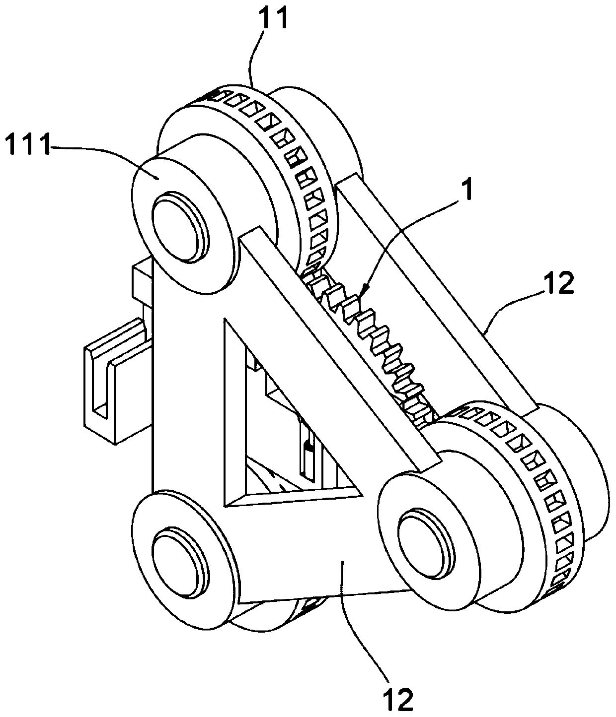
[0004] The purpose of the present invention is to provide an automatic head grooving mechanism for a ball joint for vehicles, so as to solve the problems that the ball joint is inconvenient to process and the grooves in the ball joint are not convenient for automatic production.

Method used


Image

  • An automatic head grooving mechanism for a vehicle ball joint
  • An automatic head grooving mechanism for a vehicle ball joint
  • An automatic head grooving mechanism for a vehicle ball joint

Examples


Embodiment 1

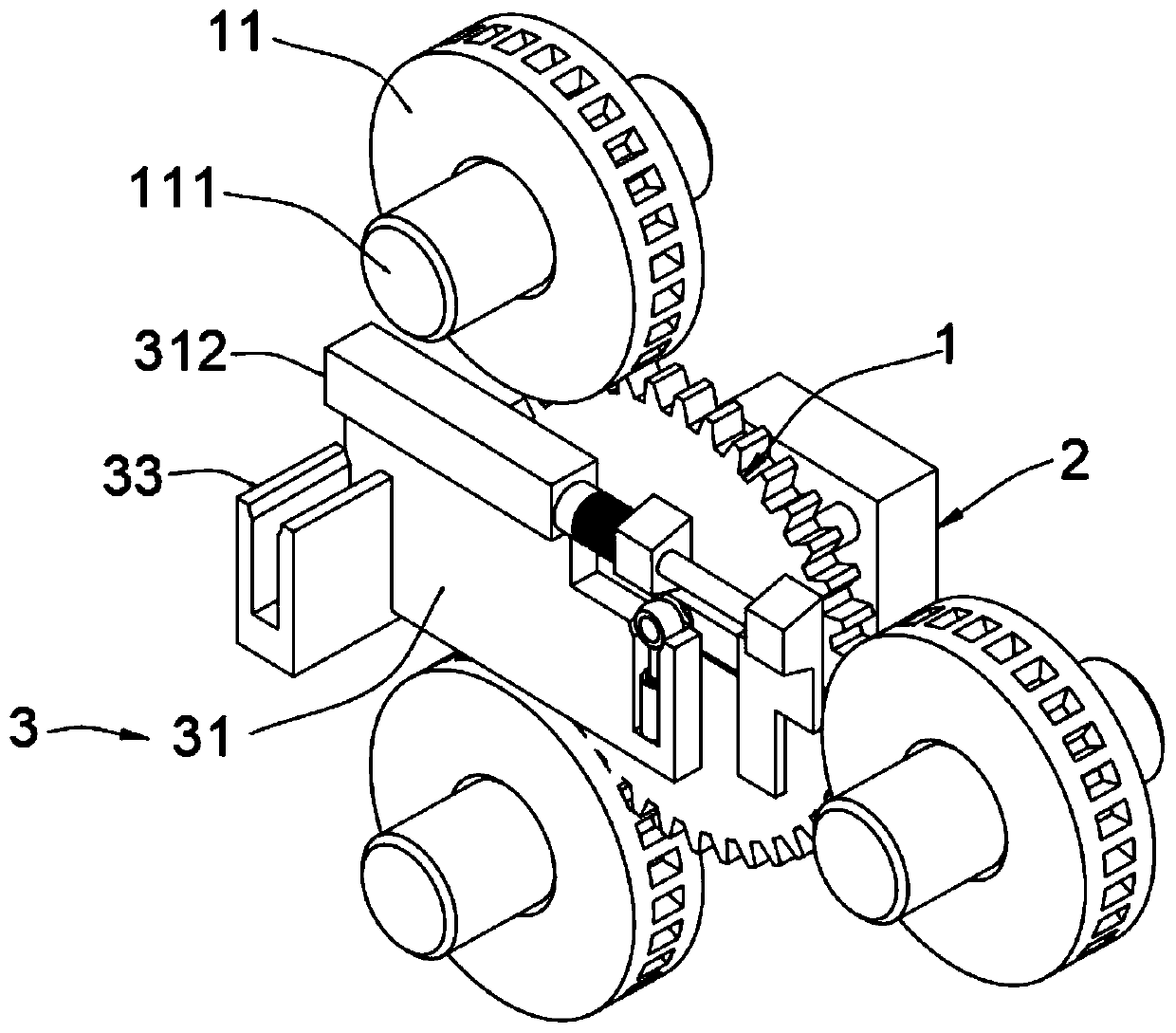
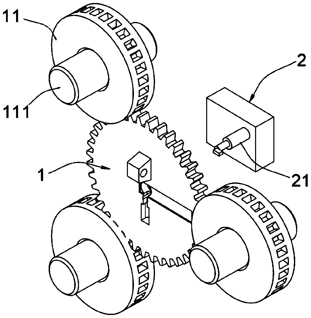
[0027] An automatic head grooving mechanism for a ball joint for vehicles, such as figure 1 , image 3 , Figure 4 with Figure 5 As shown, including the driven wheel 1, the driven wheel 1 is provided with three driving wheels 11, each driving wheel 11 is provided with a rotating shaft 111, and the front and rear end faces of the driving wheels 11 are provided with triangular baffles 12, and the triangular baffles The three tops of 12 are tightly welded with the three rotating shafts 111, and a groove 13 is arranged at the center of the front surface of the driven wheel 1, and a slotted hole 131 is arranged at the top of the bottom wall of the groove 13, and the bottom wall of the groove 13 is located at Below the slotted hole 131, several blanking holes 132 are arranged, and a slideway 14 is arranged on the side where the front surface of the driven wheel 1 is positioned at the groove 13, and the slideway 14 communicates with the groove 13, and the front surface of the driv...

Embodiment 2

[0034] As a second embodiment of the present invention, in order to facilitate the automatic production of ball joints, the inventors improved the structure of the driven wheel 1, as a preferred embodiment, such as figure 2 with Image 6 As shown, the driven wheel 1 is provided with a pusher mechanism 3, the pusher mechanism 3 includes a pusher plate 31 arranged on the front end of the driven wheel 1, one end of the pusher plate 31 is provided with a gap 311, and the gap 311 runs through the pusher plate 31. The top of the pusher plate 31 is tightly welded with an L-shaped plate 312. One end of the L-shaped plate 312 is provided with a telescopic rod 32. The telescopic rod 32 is provided with a spring 321. One end of 32 is tightly welded with a fixed block 322, the other end of the telescopic rod 32 is tightly welded with a slide plate 323, the bottom end of the pushing plate 31 is provided with a feeding block 33, and the feeding block 33 is provided with a vertical groove 3...


PUM


Abstract

The invention relates to the technical field of machines, in particular to an automatic head grooving mechanism for a spherical joint of a vehicle. The automatic head grooving mechanism comprises a driven wheel, a groove is formed in the center of the front surface of the driven wheel, the top end of the bottom wall of the groove is provided with a slotted hole, a plurality of discharging holes are formed in the positions, below the slotted hole, of the bottom wall of the groove, the rear surface of the driven wheel is provided with a pushing block, and a boring tool is tightly welded to the pushing block. According to the automatic head grooving mechanism for the spherical joint of the vehicle, a blank product of the spherical joint is placed in the groove in the driven wheel, meanwhile,the boring tool on the pushing block penetrates through the slotted hole to conduct grooving on the spherical joint, a pushing mechanism is arranged on the driven wheel to facilitate loading and unloading, the blank of the spherical joint product is placed into a vertical groove, and a pushing plate is used for pushing the blank to the position of the groove in the driven wheel for grooving processing, so that the automatic production process is achieved, and the problems that the spherical joint cannot be conveniently processed and the groove in the spherical joint cannot be conveniently andautomatically produced are solved.

Description

technical field [0001] The invention relates to the field of mechanical technology, in particular to an automatic head grooving mechanism for a ball joint for vehicles. Background technique [0002] Automobile braking system is also called automobile braking system. The function of the braking system is to make the driving car decelerate or even stop forcibly according to the driver's request, so that the stopped car can be parked stably under various road conditions and make downhill driving easier. The speed of the car remains stable. At present, various domestic automakers use more front-disc and rear-drum brake systems on small and medium-sized finished commercial vehicles. Some models use four-wheel disc brakes. Compared with drum brakes, disc brakes It is more advanced in technology, lighter in weight, better in heat dissipation performance, braking performance and adaptability to complex weather and road conditions. [0003] At present, ball joints are widely used in...

Claims


Application Information

Patent Timeline
Patent Type & Authority Patents(China)
IPC IPC(8): B23B41/00
CPCB23B41/00
Inventor 吴修远
Owner JIANGSU TIANYI PIPELINE COLD HEADING MFG
Learn More