
Excess material cutting device specially used for textile equipment

A technology for textile equipment and surplus material, applied in the field of special surplus material cutters for textile equipment, can solve the problems of waste of resources, increase the burden on staff, high labor intensity, etc., so as to avoid secondary waste, enhance cutting effect, and enhance pressure. real effect

Inactive Publication Date: 2019-01-01
陈茶仙
View PDF6 Cites 7 Cited by
  • Summary
  • Abstract
  • Description
  • Claims
  • Application Information

AI Technical Summary

Problems solved by technology

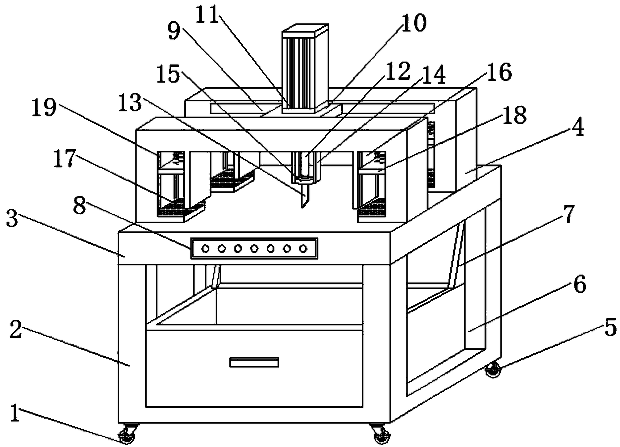
[0002] Weaving refers to a multi-scale structure processing technology of fibers or fiber aggregates. In the process of weaving, a large amount of leftover materials are usually produced. If they are discarded directly, it will not only cause waste of resources and increase costs, but also inconvenient to carry out Disposal is easy to affect the environment. In order to avoid this phenomenon, many manufacturers will use manual cutting of the remaining material into the required size to realize reuse. Due to the small size and irregular shape of the remaining material, manual cutting is not only work The efficiency is low, the labor intensity is high, and it is also prone to cutting damage, which will cause secondary waste and increase the burden on the staff

Method used

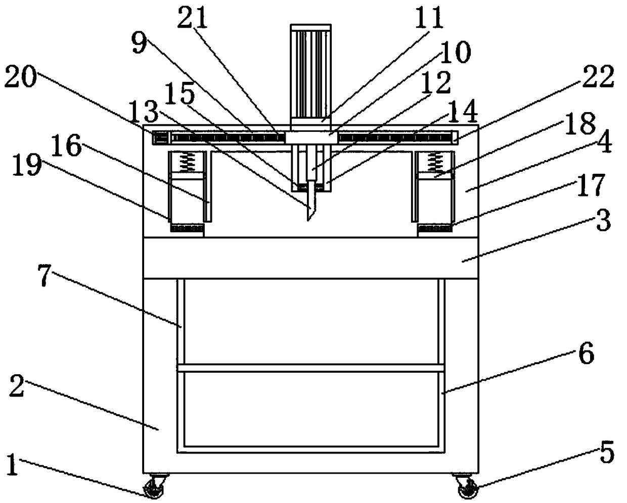
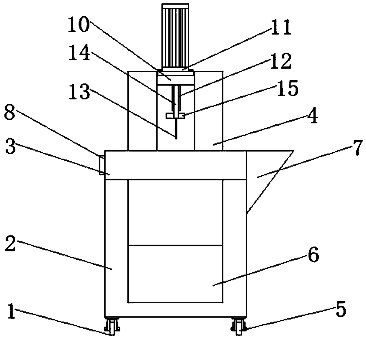

Image

  • Excess material cutting device specially used for textile equipment
  • Excess material cutting device specially used for textile equipment
  • Excess material cutting device specially used for textile equipment

Examples


Embodiment Construction

[0020] The following will clearly and completely describe the technical solutions in the embodiments of the present invention with reference to the accompanying drawings in the embodiments of the present invention. Obviously, the described embodiments are only some, not all, embodiments of the present invention. Based on the embodiments of the present invention, all other embodiments obtained by persons of ordinary skill in the art without making creative efforts belong to the protection scope of the present invention.

[0021] see Figure 1-5 , the present invention provides a technical solution: a special surplus material cutter for textile equipment, including a cutter body 1, a base 2, a cutting table 3, a bracket 4, casters 5, a collecting drawer 6, a hopper 7, and a control panel 8 , chute 9, slide plate 10, electric cylinder 11, telescopic rod 12, cutting knife 13, support plate 14, sharpening ring 15, guide plate 16, electromagnetic plate 17, pressing piece 18, slottin...


PUM


Abstract

The invention discloses an excess material cutting device specially used for textile equipment. The bottom of a cutting device body is provided with a pedestal. The top of the pedestal is provided with a cutting bench. The two sides of the top of the cutting bench are provided with supports. The top ends of the supports are provided with a chute. One end in the chute is provided with a R280 motor.One end of the R280 motor is fixedly connected to a screw. The outer side of the screw is provided with a slide plate. The top of the slide plate is provided with an electric cylinder. The bottom endof the electric cylinder is fixedly connected to a telescopic rod. The bottom of the telescopic rod is provided with a cutting knife. The two ends of the supports are provided with compaction components. The top ends of the compaction components are provided with springs. The bottom ends of the springs are installed with a pressing plate. The bottom ends of the supports are provided with an electromagnetic plate. The bottom of the pedestal is provided with truckles. In the invention, the electromagnetic plate and the pressing plate are cooperatively used, an excess material can be compacted and is prevented from moving during a cutting process, the device is simple and practical, the cutting effect of the cutting device body is increased, and simultaneously, a secondary waste is avoided,and the utilization rate of resources is increased.

Description

technical field [0001] The invention relates to the technical field of textile equipment, in particular to a special surplus material cutter for textile equipment. Background technique [0002] Weaving refers to a multi-scale structure processing technology of fibers or fiber aggregates. In the process of weaving, a large amount of leftover materials are usually produced. If they are discarded directly, it will not only cause waste of resources and increase costs, but also inconvenient to carry out Disposal is easy to affect the environment. In order to avoid this phenomenon, many manufacturers will use manual cutting of the remaining material into the required size to realize reuse. Due to the small size and irregular shape of the remaining material, manual cutting is not only work The efficiency is low, the labor intensity is high, and it is also prone to cutting damage, which will cause secondary waste and increase the burden on the staff. [0003] Therefore, it is neces...

Claims


Application Information

Patent Timeline
IPC IPC(8): D06H7/00
CPCD06H7/00
Inventor 不公告发明人
Owner 陈茶仙
Learn More