
Injection mold for automobile back light shell body

A technology for automotive rear lights and injection molds, which can be applied to household appliances, other household appliances, applications, etc., and can solve problems such as increasing costs, increasing mold size, and oil leakage into molds

Pending Publication Date: 2019-01-01
宁波如强模塑有限公司
View PDF0 Cites 4 Cited by
  • Summary
  • Abstract
  • Description
  • Claims
  • Application Information

AI Technical Summary

Problems solved by technology

[0002] Automobile rear lamp housings are all made of injection molds. According to the existing technology, there are two characteristic positions on the lower surface of automobile rear lamp housing products that are not suitable for ejection mechanisms. If an oil cylinder is used as a core puller, the cost will increase and the oil cylinder Placement and re-testing are prone to the risk of oil leakage into the mold, and will increase the size of the mold

Method used


Image

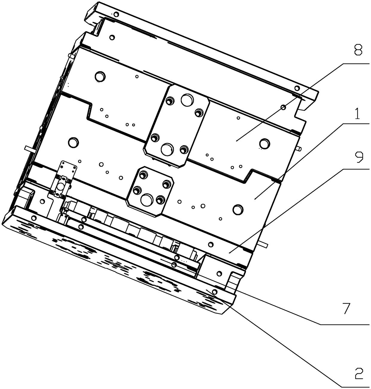
  • Injection mold for automobile back light shell body
  • Injection mold for automobile back light shell body
  • Injection mold for automobile back light shell body

Examples


Embodiment Construction

[0019] The present invention will be further described below in conjunction with the accompanying drawings and specific embodiments.

[0020] As shown in the figure, the present invention provides a kind of injection mold that is used for automobile rear light housing, comprises upper formwork 8, lower formwork 1 and die foot 2 that is fixed below lower formwork 1, and described upper formwork 8 is positioned at lower formwork 1 On the upper surface, a push plate 7 is provided between the mold foot 2 and the lower formwork 1, and the push plate 7 can be slidably fitted in the mold foot 2. The upper surface of the lower formwork 1 and the lower surface of the upper formwork 8 There is a cavity for forming the product 3 between them, and the lower surface of the product 3 is respectively provided with a first opening groove 5 and a second opening groove 6, and the first opening groove 5 is located above the second opening groove 6 , the center line of the first open slot 5 forms...


PUM


Abstract

The invention discloses an injection mold for an automobile back light shell body. The injection mold comprises an upper template, a lower template and a mold leg which fixed below the lower template,wherein the upper template is located on the upper surface of the lower template; a push plate is arranged between the mold leg and the lower template; the push plate is arranged in the mold leg in asliding match manner; a mold cavity for molding a product is arranged between the upper surface of the lower template and the lower surface of the upper template; a first opening groove and a secondopening groove are formed in the lower surface of the product respectively; the first opening groove is located above the second opening groove; a first included angle is formed between the central line of the first opening groove and a vertical plane; a second included angle is formed between the central line of the second opening groove and the vertical plane. The injection mold provided by theinvention has the advantages that the cost is low, oil does not seep into the mold and the size of the mold is not increased.

Description

technical field [0001] The invention relates to the field of injection molds, in particular to an injection mold used for automobile rear lamp housings. Background technique [0002] Automobile rear lamp housings are all made of injection molds. According to the existing technology, there are two characteristic positions on the lower surface of automobile rear lamp housing products that are not suitable for ejection mechanisms. If an oil cylinder is used for core pulling, the cost will increase and the oil cylinder Placement and re-testing are prone to the risk of oil leakage into the mold and will increase the size of the mold. Contents of the invention [0003] The technical problem to be solved by the present invention is to overcome the above defects of the prior art and provide an injection mold with low cost, no oil seeping into the mold and no increase in mold size. [0004] The technical solution adopted by the present invention is: an injection mold for automobil...

Claims


Application Information

Patent Timeline
Patent Type & Authority Applications(China)
IPC IPC(8): B29C45/33B29C45/40B29C45/44B29L31/30
CPCB29C45/33B29C45/4005B29C45/44B29C2045/445B29L2031/7472B29L2031/30
Inventor 史武龙董士奇
Owner 宁波如强模塑有限公司
Learn More