
A collaborative low-carbon planning method for multi-energy systems based on carbon emission flow

A system planning and multi-energy technology, applied in the direction of system integration technology, information technology support system, data processing application, etc., can solve the problem of inability to distinguish the carbon emission responsibility of multi-energy systems, not fully utilizing the low-carbon emission reduction benefits of multi-energy systems, Less consideration of carbon emission limits and other issues

Active Publication Date: 2022-02-18
TSINGHUA UNIV
View PDF5 Cites 0 Cited by
  • Summary
  • Abstract
  • Description
  • Claims
  • Application Information

AI Technical Summary

Problems solved by technology

[0003] At present, most of the multi-energy system planning problems use the economic optimization as the objective function, consider the constraints of the conventional energy network equations, and seldom consider the limitation of carbon emissions. Carbon emission responsibilities of regional multi-energy systems

Method used


Image

  • A collaborative low-carbon planning method for multi-energy systems based on carbon emission flow
  • A collaborative low-carbon planning method for multi-energy systems based on carbon emission flow
  • A collaborative low-carbon planning method for multi-energy systems based on carbon emission flow

Examples


Embodiment 1

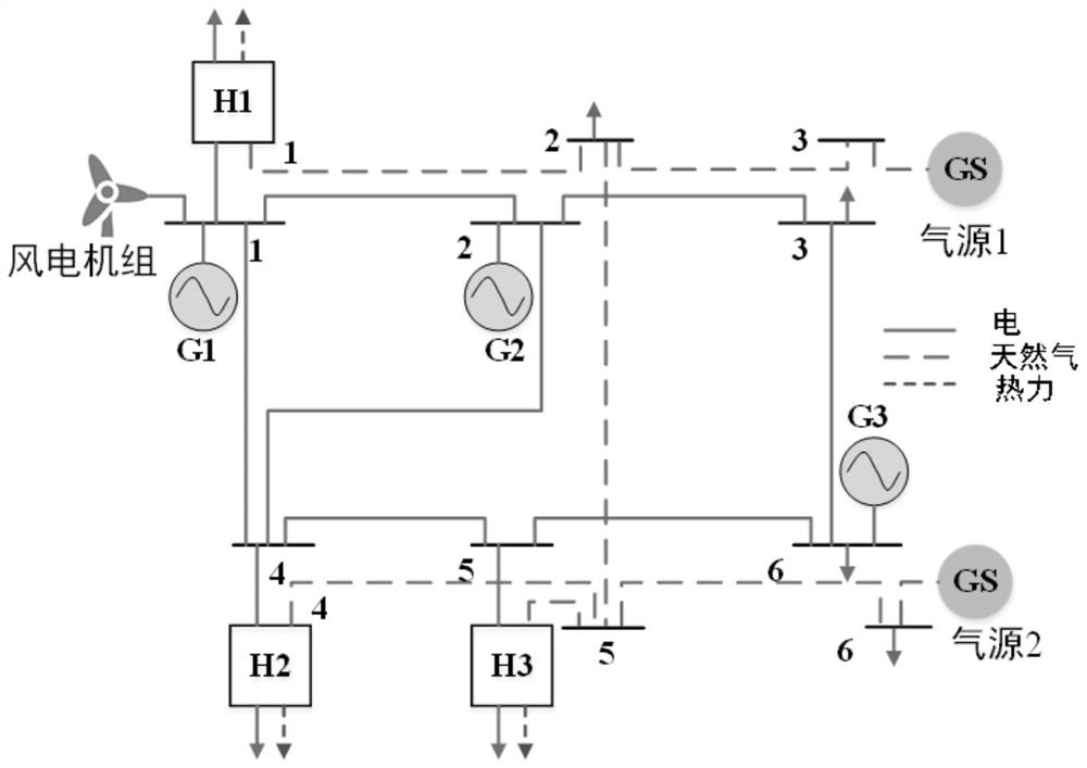
[0210] The following takes a 6-node system as an example for planning, and the application examples are as follows:

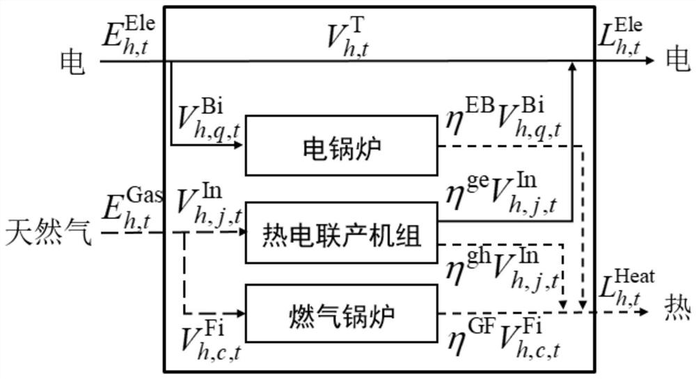
[0211] This example system is a 6-node multi-energy system, and the topology of the cross-regional multi-energy network is as follows image 3 shown. The system includes 4 generating units (one of which is a wind turbine), 2 gas sources and 3 regional multi-energy systems (H1~H3). The upper cross-regional multi-energy system includes a wind turbine with a capacity of 50MW to be built, 8 power transmission lines to be built and 19 natural gas pipelines to be built; each regional-level multi-energy system (energy hub) includes an existing Construction of electric boilers, 1 built gas boiler and 3 cogeneration units to be built. Consider the load profiles for two typical days in winter and summer, each with a duration of 6 months.

[0212] The overall carbon emission limit is set to be 710000tCO2, and the planning results of the multi-energy system obtained by ...


PUM


Abstract

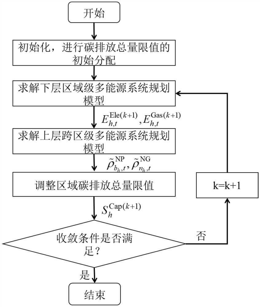
The invention discloses a multi-energy system collaborative low-carbon planning method based on carbon emission flow, which belongs to the technical field of power system optimization analysis. The method includes: initial allocation of the total carbon emission limit; using a regional multi-energy system model to optimize the optimal configuration of the regional multi-energy system; using a cross-regional multi-energy system model to optimize the inter-regional multi-energy system power transmission lines, natural gas pipelines and power points; solve the carbon emission flow distribution of the multi-energy system to determine the carbon emission of each regional multi-energy system, and compare the total carbon emission limit of each region and the calculated carbon emission of the regional multi-energy system , adjust the total carbon emission limit of each region, and re-plan, and realize the coordinated low-carbon planning of multi-energy system through iteration. The present invention obtains an overall optimal coordinated low-carbon planning method for a multi-energy system by rationally distributing the total carbon emission limit value, thereby laying a good foundation for the low-carbon planning of the energy system.

Description

technical field [0001] The invention belongs to the technical field of power system optimization analysis, and in particular relates to a multi-energy system collaborative low-carbon planning method based on carbon emission flow. Background technique [0002] As energy issues and climate change issues become increasingly prominent, achieving low-carbon development and reducing excessive consumption of fossil energy has gradually become a common goal of human society. The core of low-carbon development is technological innovation, institutional innovation, and changes in the concept of development, which will involve the readjustment of production models, lifestyles, and values, and are closely related to national rights and interests. The multi-energy system realizes the synergistic effect of different energy systems by coupling various forms of energy such as electricity, heat, and natural gas in different time and space links, which can improve the overall utilization effi...

Claims


Application Information

Patent Timeline
Patent Type & Authority Patents(China)
IPC IPC(8): G06F30/20
CPCG06Q10/04G06Q10/06313G06Q50/06G06F2219/10Y04S10/50Y02E40/70
Inventor 程耀华张宁康重庆王毅杨经纬黄武靖
Owner TSINGHUA UNIV
Learn More