Method and device for realizing refraction multi-wave tomography inversion, and processing terminal

A tomographic inversion and multiple wave technology, applied in seismic signal processing and other directions, can solve the problems of difficulty in picking up reflected waves, a large number of calculations, and low reliability of picking results.

Active Publication Date: 2018-12-28
GUANGZHOU MARINE GEOLOGICAL SURVEY
View PDF2 Cites 7 Cited by
  • Summary
  • Abstract
  • Description
  • Claims
  • Application Information

AI Technical Summary

Problems solved by technology

[0009] (1) The signal-to-noise ratio of the first arrival refraction is low at far offset distances, and the reliability of the picking results is low. In order to practically apply these refraction distances at far offset distances, a large uncertainty parameter has to be set
[0010] (2) In the scheme of using reflected wave travel time for inversion, it is necessary to associate the picked reflected wave travel time with a certain reflecting interface, which will cause a large uncertainty
Moreover, in OBS data with large offsets, it is difficult to pick up the reflected wave travel time
[0011] (3) It is very potential to use refracted multiple waves of OBS data to perform tomographic inversion, but there is no good plan at present
For the scheme proposed by Wan Kuiyuan et al., in most of the actual data, it is difficult to identify the refracted waves reflected multiple times in the sediment layer, and in the inversion process, it is necessary to determine the reflection interface, which will cause great uncertainty sex
However, the scheme proposed by Bharadwaj et al. is only applicable to the first wave sliding along the interface, but not to the refracted wave in other situations.
In addition, the conversion of refracted multiples to first-arrival refraction by seismic interferometry requires a large amount of computation

Method used


Image

  • Method and device for realizing refraction multi-wave tomography inversion, and processing terminal
  • Method and device for realizing refraction multi-wave tomography inversion, and processing terminal
  • Method and device for realizing refraction multi-wave tomography inversion, and processing terminal

Examples


Embodiment 1

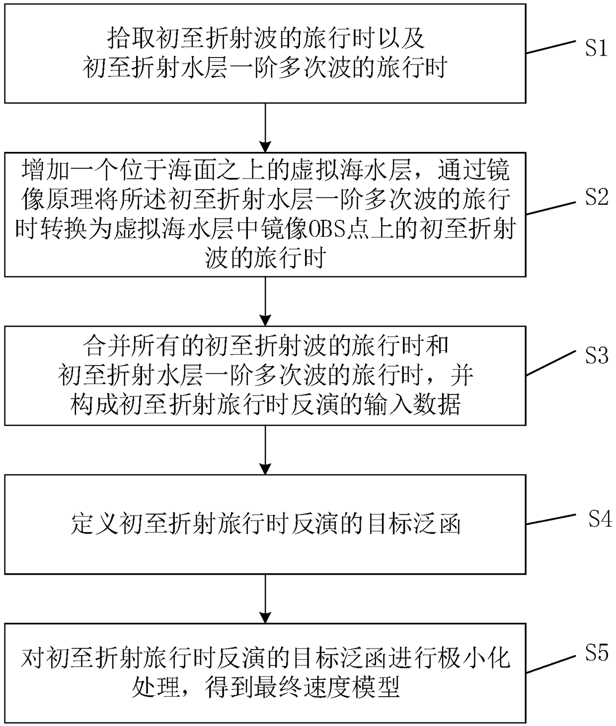
[0092] Such as figure 1 As shown, the present invention discloses a method for realizing refraction multiple wave tomographic inversion, which is characterized in that it comprises the following steps:

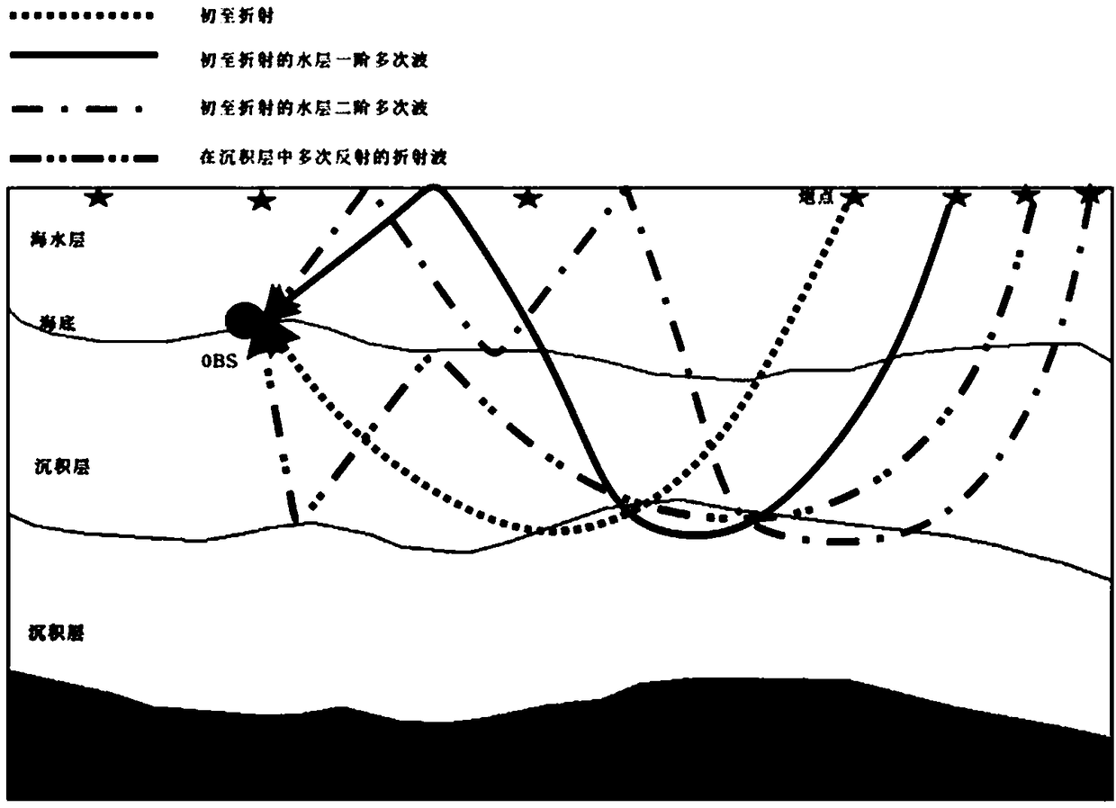
[0093] S1. When picking up the travel time of the refracted wave at the first arrival, denote it as t obs , when picking up the travel of the first-order multiples at the first arrival in the refracted water layer, it is denoted as

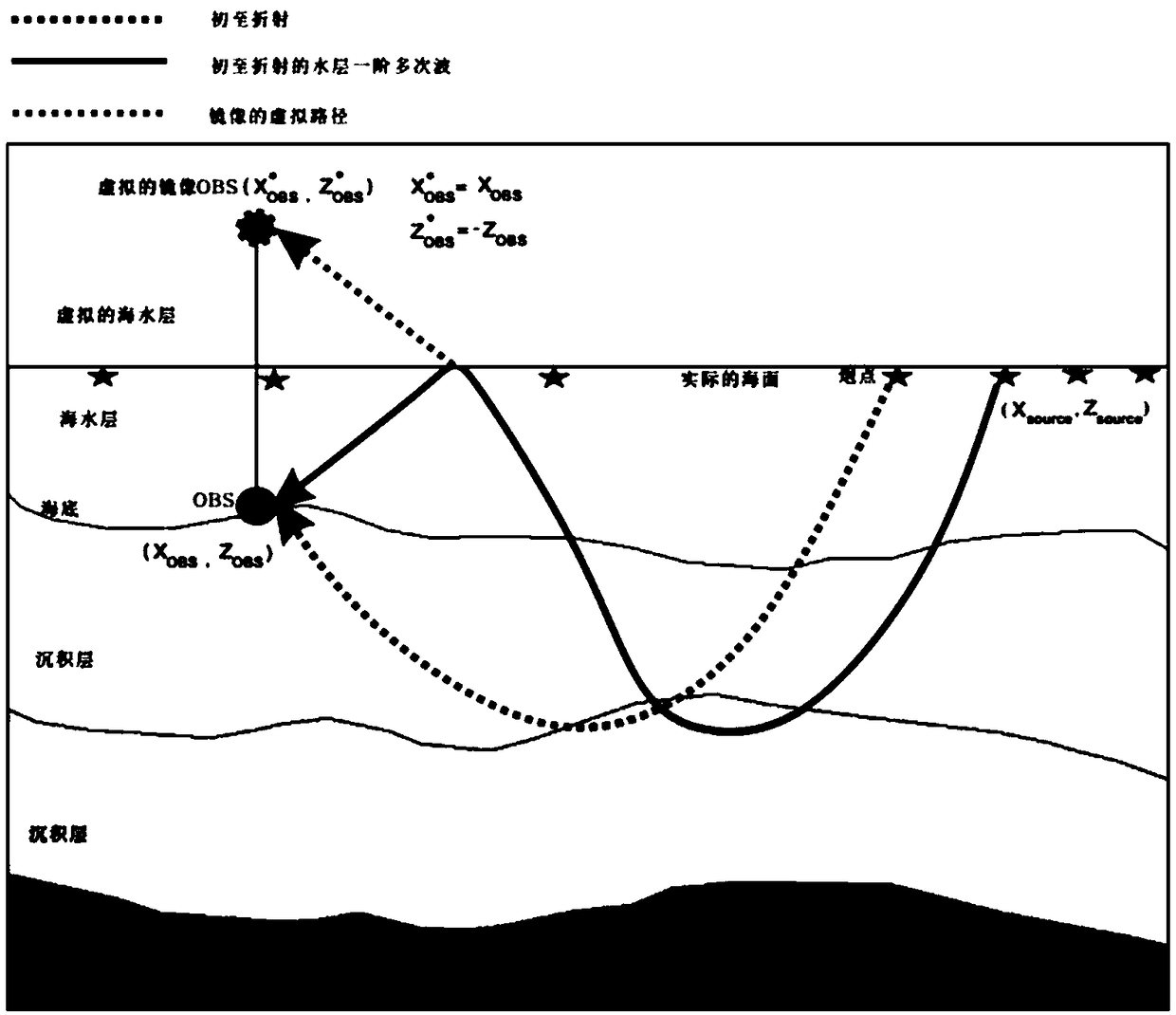
[0094] S2. Add a virtual seawater layer above the sea surface, and use the mirror image principle to Converted to the travel time of the first-arrival refracted wave on the mirrored OBS point in the virtual seawater layer, it is recorded as

[0095] S3, merge all t obs and denoted as T obs , the T obs Constituting the input data for the inversion of first-arrival refraction traveltime;

[0096] S4. Define the target functional of the first-arrival refraction travel time inversion as where m is the velocity model, T cal (m) The actu...

Embodiment 2

[0123] Such as Figure 9 As shown, the present invention discloses a device for realizing refraction multiple wave tomographic inversion, including the following modules:

[0124] The pick-up module is used to pick up the travel time of the first-arrival refracted wave, denoted as t obs , when picking up the travel of the first-order multiples at the first arrival in the refracted water layer, it is denoted as

[0125] The conversion module is used to add a virtual seawater layer above the sea surface, and the described Converted to the travel time of the first-arrival refracted wave on the mirrored OBS point in the virtual seawater layer, it is recorded as

[0126] Merge module for merging all t obs and denoted as T obs , the T obs Constituting the input data for the inversion of first-arrival refraction traveltime;

[0127] definition module for defining the target functional for first-arrival refraction traveltime inversion as where m is the velocity model, T...

Embodiment 3

[0142] Such as Figure 10 As shown, the present invention discloses a processing terminal, including:

[0143] memory for storing program instructions;

[0144] a processor for executing the program instructions to perform the following steps:

[0145] S1. When picking up the travel time of the refracted wave at the first arrival, denote it as t obs , when picking up the travel of the first-order multiples at the first arrival in the refracted water layer, it is denoted as

[0146] S2. Add a virtual seawater layer above the sea surface, and use the mirror image principle to Converted to the travel time of the first-arrival refracted wave on the mirrored OBS point in the virtual seawater layer, it is recorded as

[0147] S3, merge all t obs and denoted as T obs , the T obs Constituting the input data for the inversion of first-arrival refraction traveltime;

[0148] S4. Define the target functional of the first-arrival refraction travel time inversion as where ...


PUM


Abstract

The invention discloses a method and device for realizing refraction multi-wave tomography inversion, and a processing terminal. The method comprises the following steps: S1, when picking up a travelof the first-to-refractive wave, recording the travel as tobs, and when picking up a first-order multi-wave travel of the first-to-refractive water layer, recording the travel as FORMULA referred; S2,adding a virtual seawater layer above the sea surface, and converting the FORMULA referred into the travel of the first-to-refractive wave on a mirrored OBS point in the virtual seawater layer by themirror principle, recording the travel as FORMULA referred; S3, merging all the tobses and FORMULAE referred, recording as Tobs, wherein the Tobs constitutes the input data of inverted during the first-to-refractive travel; S4, defining a target functional inverted during the first-to-refractive travel; and S5, miniaturizing the target functional inverted during the first-to-refractive travel toobtain a final velocity model. The method and device for realizing refraction multi-wave tomography inversion, and the processing terminal realize the purpose of performing tomography inversion by using the rich, clear and reliable refraction multi-waves in the OBS data based on the mirror principle.

Description

technical field [0001] The invention relates to the technical field of tomographic inversion by using refracted multiple waves. Background technique [0002] Velocity and interface shape parameters of deep ocean geological structures are key parameters for understanding ocean basin evolution and geodynamics. At present, the original observation data is mainly obtained by stimulating a large-capacity source on the sea surface and receiving it by an ocean bottom seismograph (OBS) on the seabed. The offset distance of OBS data is relatively large, up to hundreds of kilometers, and records refracted and reflected waves from sedimentary layers and crust-mantle boundaries. In laboratory analysis, the velocity and shape parameters of subsurface structures are mainly obtained through travel time inversion. There are also some examples of using full waveform inversion to obtain the velocity structure, but this method has very high requirements on the quality of the original data, a...

Claims


Application Information

Patent Timeline
Patent Type & Authority Applications(China)
IPC IPC(8): G01V1/30
Inventor 刘斌
Owner GUANGZHOU MARINE GEOLOGICAL SURVEY
Why Eureka
Try Eureka