Cutting device with leftover material collecting function for production of mechanical equipment

A technology of mechanical equipment and cutting device, which is applied in the field of cutting devices with scrap collecting function for the production of mechanical equipment, can solve the problems such as the cutting knife is not cooled, the scrap scrap is not collected, the shock resistance coefficient is low, etc. Continue to operate normally, improve practicability, and improve the effect of anti-vibration coefficient

Active Publication Date: 2018-12-28
常德瑞齐隆科技发展有限公司
View PDF6 Cites 7 Cited by
  • Summary
  • Abstract
  • Description
  • Claims
  • Application Information

AI Technical Summary

Problems solved by technology

A mechanical cutting device in the above-mentioned patent has the following disadvantages: the device has a low shock resistance coefficient, and does not collect corner materials, and the cutting knife that has been working for a long time has not been cooled. At the same time, the cutting angle of the device is relatively fixed, and the practicability is relatively low. low, and the above-mentioned patents cannot solve such problems, therefore, there is an urgent need for a cutting device with corner material collection function for mechanical equipment production

Method used


Image

  • Cutting device with leftover material collecting function for production of mechanical equipment
  • Cutting device with leftover material collecting function for production of mechanical equipment
  • Cutting device with leftover material collecting function for production of mechanical equipment

Examples


Embodiment Construction

[0026] The technical solutions in the embodiments of the present invention will be clearly and completely described below in conjunction with the accompanying drawings in the embodiments of the present invention. Obviously, the described embodiments are only a part of the embodiments of the present invention, rather than all the embodiments.

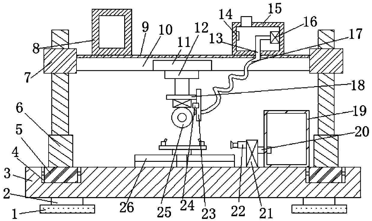
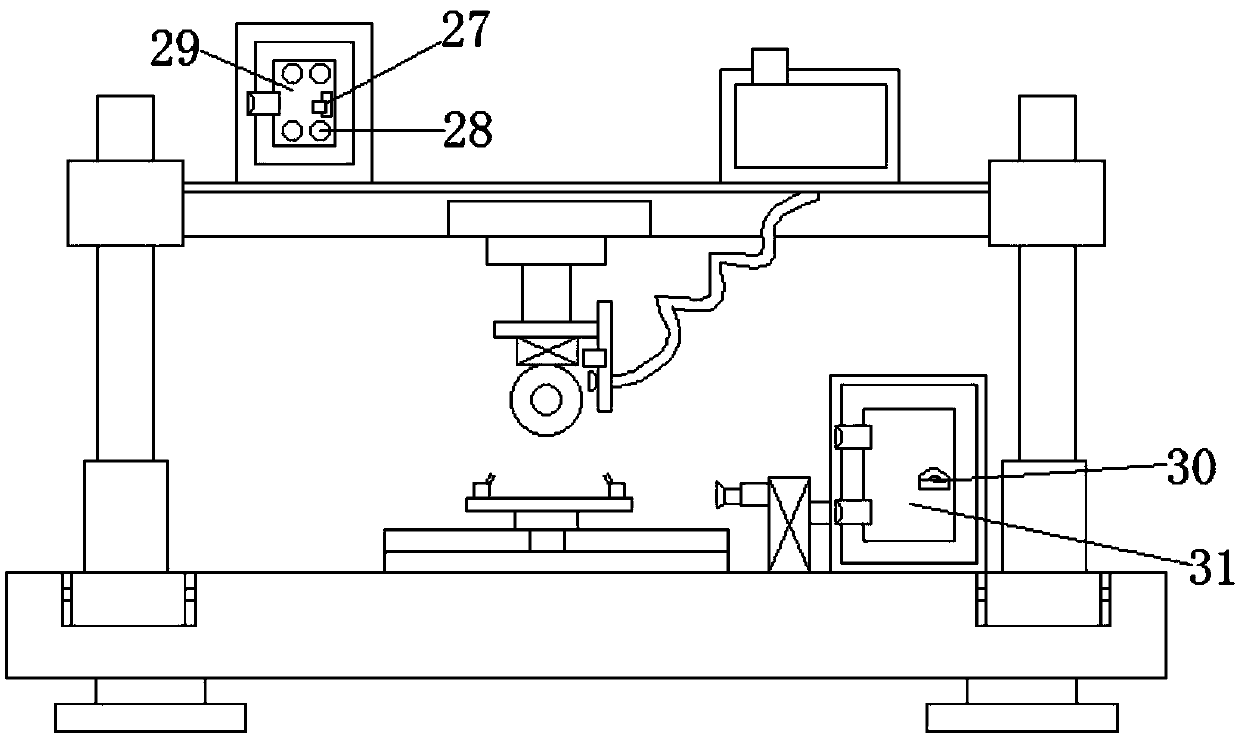
[0027] Reference Figure 1-5 , A cutting device with corner material collection function for the production of mechanical equipment, including a base 3, the four corners of the bottom of the base 3 are all fixed with support blocks 2 through bolts, and the bottom outer walls of the four support blocks 2 are fixed with anti-vibration pads 1 through screws. , Can improve the anti-vibration coefficient of the device, and also enhance the stability of the device. The outer walls on both sides of the top of the base 3 are provided with first slide grooves, and the inner walls of the two first slide grooves are fixed with slide rails 4 by bolts, w...


PUM


Abstract

The invention belongs to the technical field of cutting devices, and particularly relates to a cutting device with a leftover material collecting function for production of mechanical equipment. Aiming at the problems that a device is low in shockproof coefficient, leftover materials are not collected, a cutting knife working for a long time is not cooled either, meanwhile, the cutting angle of the device is fixed, and practicability is relatively low, the following scheme is proposed, specifically, the cutting device comprises a base, supporting blocks are fixed to the outer walls of the fourcorners of the bottom of the base through bolts correspondingly, and shockproof pads are fixed to the outer walls of the bottoms of the four supporting blocks through screws correspondingly; and first sliding grooves are formed in the outer walls of the two sides of the top of the base correspondingly, sliding rails are fixed to the inner walls of the two first sliding grooves through bolts correspondingly, and the inner walls of the two sliding rails are slidably connected with first sliding blocks. According to the cutting device, the shockproof coefficient of the cutting device can be increased, the stability of the cutting device is also improved, the cutting requirements of different mechanical equipment are met, thus the cutting device is more practical, and the cutting quality andefficiency are improved advantageously.

Description

Technical field [0001] The invention relates to the technical field of cutting devices, in particular to a cutting device with corner material collection function for the production of mechanical equipment. Background technique [0002] There are many types of mechanical equipment. When the mechanical equipment is running, some of its parts or even itself can perform different forms of mechanical movement. Mechanical equipment is composed of driving device, speed changing device, transmission device, working device, braking device, protection device, lubrication system, cooling system and other parts. The main products of the machinery industry include the following 12 categories: agricultural machinery, construction machinery, petrochemical general machinery, electrical machinery, machine tools, automobiles, etc. [0003] After searching, the Chinese patent application number CN201621235571.4 discloses a mechanical cutting device, including a box body, the top of the box body is ...

Claims


Application Information

Patent Timeline
Patent Type & Authority Applications(China)
IPC IPC(8): B23D19/00B23D33/00B23Q11/00B23Q11/10
CPCB23D19/00B23D33/00B23Q11/0046B23Q11/10
Inventor 黄定辉
Owner 常德瑞齐隆科技发展有限公司
Why Eureka
Try Eureka