
In-vivo accumulated liquid steady-pressure drainage device for operations

A technology for surgery and effusion, applied in the direction of suction equipment, other medical equipment, hypodermic injection equipment, etc., can solve the problems of unstable negative pressure, continuous drainage, low work efficiency, etc., and achieves ingenious structure and simple operation , to enhance the effect of stability

Active Publication Date: 2018-12-21
THE AFFILIATED HOSPITAL OF QINGDAO UNIV
View PDF7 Cites 19 Cited by
  • Summary
  • Abstract
  • Description
  • Claims
  • Application Information

AI Technical Summary

Problems solved by technology

[0002] Negative pressure drainage is widely used in clinical practice. It is mainly aimed at postoperative patients. There are many pressure drainage devices, such as artificial negative pressure drainage balls, artificial negative pressure drainage bottles, central negative pressure drainage bottles, etc.; artificial negative pressure drainage devices will not be able to stabilize the negative pressure during the negative pressure manufacturing process and adjust the negative pressure according to the patient's own situation; The central negative pressure drainage bottle can only rely on external power such as a negative pressure suction device to generate negative pressure. Pressure drainage device, after the drainage fluid enters the negative pressure chamber, negative pressure drainage cannot be performed. After a drainage, the drainage device needs to be removed to discharge the drainage fluid and then the drainage can be performed. The drainage work can only be done intermittently, not continuous drainage, and the work efficiency is low.

Method used


Image

  • In-vivo accumulated liquid steady-pressure drainage device for operations
  • In-vivo accumulated liquid steady-pressure drainage device for operations
  • In-vivo accumulated liquid steady-pressure drainage device for operations

Examples


Embodiment Construction

[0014] The specific implementation manners of the present invention will be described in further detail below in conjunction with the accompanying drawings.

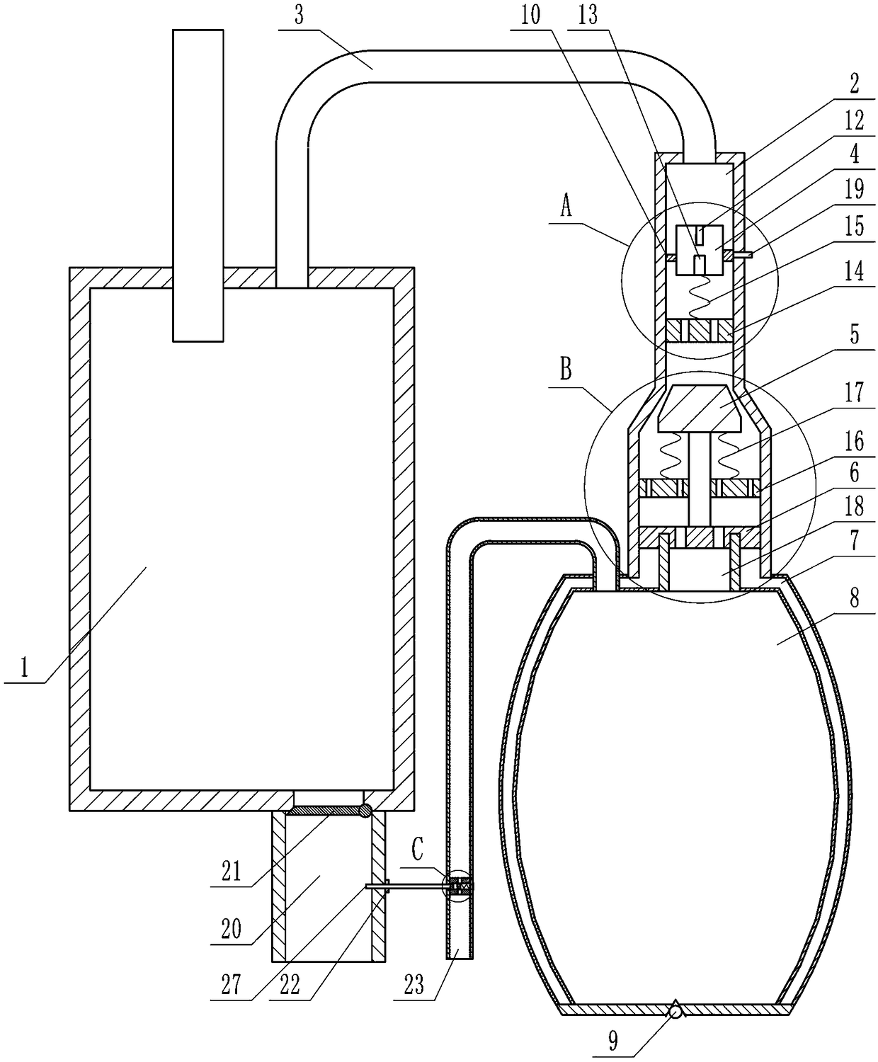
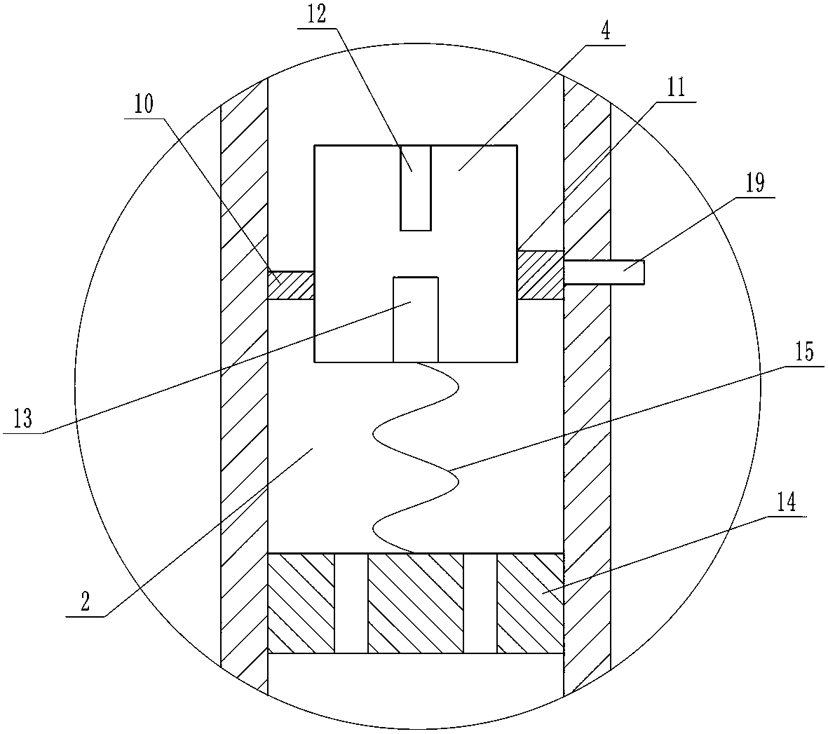
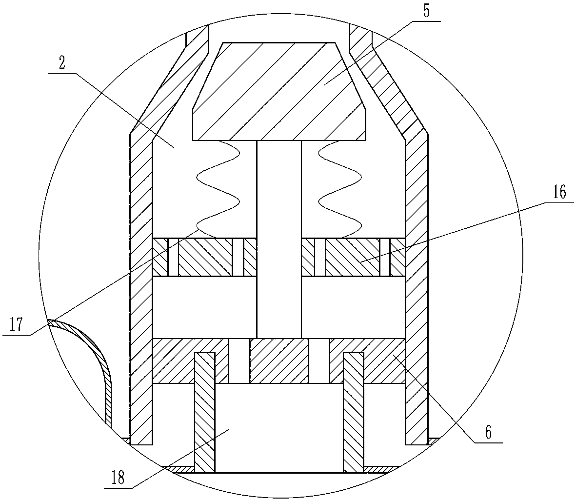
[0015] Depend on Figure 1-8 It can be seen that the present invention includes a drainage bottle 1, the right side of the drainage bottle 1 is provided with a vertically placed air guide cylinder 2, the drainage bottle 1 communicates with the air guide cylinder 2 through the air guide tube 3, and the air guide cylinder 2 is equipped with a guide tube located above the air guide cylinder 2. The air column 4 and the sealing block 5 located below the air guide cylinder 2, the lower end of the seal block 5 is connected with the sealing piston 6 placed in the air guide cylinder 2, the air guide column 4 and the sealing block 5 can slide up and down, and the lower end of the air guide cylinder 2 is connected with a Double-layer airbag structure, the double-layer airbag structure includes an outer airbag 7 connected to the low...


PUM


Abstract

The invention provides an in-vivo accumulated liquid steady-pressure drainage device for operations. The change of a negative pressure scope can be controlled, the device is applicable to various emergencies, there is no need to stop a drainage process for replacing a drainage bottle, the operation process is effectively simplified, and the negative pressure drainage effect is improved. Accordingto the technical scheme, the device includes the drainage bottle, an air guiding cylinder is arranged on the right side of the drainage bottle, the drainage bottle is communicated with the air guidingcylinder through an air guiding tube, an air guiding column and a sealing block are arranged in the air guiding cylinder, and a sealing piston is connected to the lower end of the sealing block; thelower end of the air guiding cylinder is connected with an outer airbag and an inner airbag, a check valve is installed on the bottom wall of a double-layer airbag structure, a sealing space is formedbetween the outer airbag and the sealing piston, and a gas channel is formed by making the inner airbag communicated with the air guiding cylinder. By extruding the double-layer airbag structure to switch into a negative pressure state, the air guiding column slides down, correspondingly gas in the drainage bottle flows into the inner airbag, and therefore the interior of the drainage bottle is switched into the negative pressure state. The device has the advantages of being novel in concept, ingenious in structure, easy to operate, convenient to use and the like.

Description

technical field [0001] The invention relates to the field of medical devices, in particular to a pressure-stabilizing and drainage device for intracorporeal fluid accumulation used in surgery. Background technique [0002] Negative pressure drainage is widely used in clinical practice. It is mainly aimed at postoperative patients. There are many pressure drainage devices, such as artificial negative pressure drainage balls, artificial negative pressure drainage bottles, central negative pressure drainage bottles, etc.; artificial negative pressure drainage devices will not be able to stabilize the negative pressure during the negative pressure manufacturing process and adjust the negative pressure according to the patient's own situation; The central negative pressure drainage bottle can only rely on external power such as a negative pressure suction device to generate negative pressure. Pressure drainage device, after the drainage fluid enters the negative pressure chamber...

Claims


Application Information

Patent Timeline
IPC IPC(8): A61M1/00
CPCA61M1/0023A61M2205/3331A61M1/74
Inventor 毛新梅
Owner THE AFFILIATED HOSPITAL OF QINGDAO UNIV
Learn More