
A telescopic rod for a photovoltaic solar support

A photovoltaic solar energy and telescopic rod technology, which is applied in the photovoltaic solar energy field, can solve the problems of low frame installation efficiency, simple structure, and small scope of application of solar brackets.

Inactive Publication Date: 2018-12-18
合肥利仁信息科技有限公司
View PDF0 Cites 4 Cited by
  • Summary
  • Abstract
  • Description
  • Claims
  • Application Information

AI Technical Summary

Problems solved by technology

[0003] The strength and toughness of the solar bracket directly affect the quality of the solar bracket. However, the structure of the previous solar bracket is simple, and the orientation of the solar panel cannot be adjusted, resulting in a small range of application of the solar bracket; , it is necessary to drill bolt holes on the frame and fix the frame with bolts, while more bolts need to be installed on a solar bracket, which leads to low installation efficiency of the frame and increases the labor intensity of workers

Method used


Image

  • A telescopic rod for a photovoltaic solar support
  • A telescopic rod for a photovoltaic solar support
  • A telescopic rod for a photovoltaic solar support

Examples


Embodiment 1

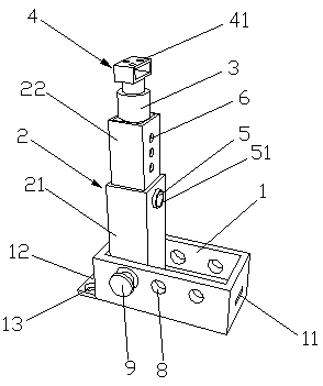
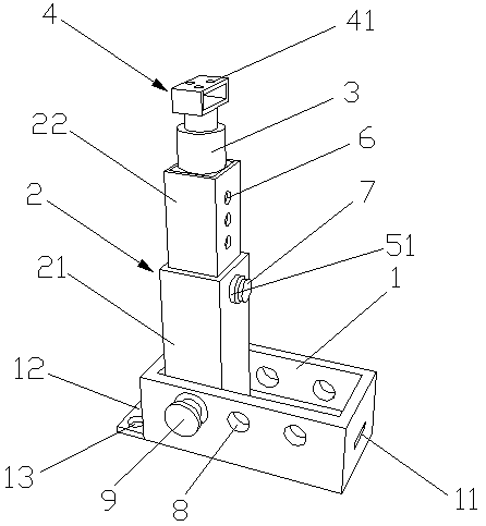
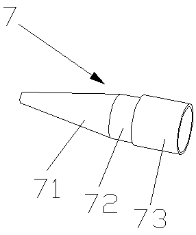
[0023] like Figure 1-3 As shown, a telescopic rod for photovoltaic solar support of the present invention includes a telescopic rod base 1, the telescopic rod base 1 is a groove-shaped structure with an open top, and a telescopic rod body 2 is also arranged in the telescopic rod base 1, and the telescopic rod body 2 includes a first One rod body 21 and the second rod body 22, one end of the first rod body 21 is movably arranged in the telescopic rod base 1, the other end of the first rod body 21 is movably connected with an end of the second rod body 22, and the other end of the second rod body 22 is also A damping rod 3 is fixedly arranged, and a mounting base 4 is arranged on the damping rod 3, and a first fixing hole 5 is also arranged on the side wall of the other end of the first rod body 21, and a hole sleeve 51 is fixedly arranged in the first fixing hole 5, and the hole A fixed pin 7 is movable in the sleeve 51. The fixed pin 7 includes a pin end 71 and a pin tail 72....

Embodiment 2

[0025] The telescopic rod base 1 is a groove-shaped structure with an opening at the top. The telescopic rod base 1 is also provided with a telescopic rod body 2. The telescopic rod body 2 includes a first rod body 21 and a second rod body 22. One end of the first rod body 21 is movably arranged on the telescopic rod base. 1, the other end of the first rod body 21 is flexibly connected to one end of the second rod body 22, and the other end of the second rod body 22 is also fixedly provided with a damping rod 3, and the damping rod 3 is provided with a mounting seat 4, and the first rod body 21 The side wall of the other end is also provided with a first fixing hole 5, and a hole sleeve 51 is fixedly arranged in the first fixing hole 5, and a fixed pin shaft 7 is movably arranged in the hole sleeve 51, and the fixed pin shaft 7 includes a pin shaft end 71 And the pin tail 72, the pin end 71 is a conical structure, the pin tail 72 is a cylindrical structure, the large diameter e...


PUM


Abstract

A telescopic rod for a photovoltaic solar support particularly relates to the field of photovoltaic solar energy technology, includes a telescopic rod base, A telescopic rod body is also arrange in that base of the telescopic rod, A telescopic rod body include a first rod body and a second rod body, one end of the first rod body is movably arranged in the base of the telescopic rod, the other endof the first rod body is movably connected with one end of the second rod body, a damping rod is fixedly arranged on the other end of the second rod body, A mount is arranged on the damping rod, A lateral wall of that other end of the first rod body is also provide with a first fixing hole, The first fixing hole is fixedly provided with a hole sleeve, and the interior of the hole sleeve is movablyprovided with a fixed pin shaft. The fixed pin shaft comprises a pin shaft end part and a pin shaft tail part, a large diameter end of the pin shaft end part is fixedly connected with one end of thepin shaft tail part, a ring body sleeve is movably arranged on the other end of the pin shaft tail part, and a plurality of second fixed holes are also arranged on the side walls of the second rod body. The invention has the advantages that the height can be adjusted according to the actual use needs, and the fixation is firm, and the like.

Description

technical field [0001] The invention relates to the technical field of photovoltaic solar energy, in particular to a telescopic rod for a photovoltaic solar support. Background technique [0002] As a low-carbon renewable energy source, solar energy can be used for free, without transportation, and has no pollution to the environment. Compared with conventional energy sources, it is easy to use and low in cost. Solar photovoltaic panel components are used to directly convert solar energy into electrical energy, supply power to electrical equipment or transmit electrical energy to the grid, and meet the needs of today's society for electrical energy. [0003] The strength and toughness of the solar bracket directly affect the quality of the solar bracket. However, the structure of the previous solar bracket is simple, and the orientation of the solar panel cannot be adjusted, resulting in a small range of application of the solar bracket; , It is necessary to drill bolt hole...

Claims


Application Information

Patent Timeline
IPC IPC(8): H02S20/30
CPCH02S20/30Y02E10/50
Inventor 张文凤
Owner 合肥利仁信息科技有限公司
Learn More