
A lightning rod vibration absorbing device for a substation

A vibration damping device and lightning rod technology, applied in the installation of cables, electrical components, installation of lighting conductors, etc., can solve the problems of fracture and damage of lightning rod connection parts, affecting the normal operation of substations, and metal fatigue of lightning rods, achieving reasonable stress and structure. Simple, wind-induced vibration reduction effect

Pending Publication Date: 2018-12-18
NORTHWEST ELECTRIC POWER DESIGN INST OF CHINA POWER ENG CONSULTING GROUP
View PDF6 Cites 3 Cited by
  • Summary
  • Abstract
  • Description
  • Claims
  • Application Information

AI Technical Summary

Problems solved by technology

The lightning rods of substations in areas with high frequency of strong winds such as Northwest my country, North China, and Northeast China are affected by the combined influence of strong wind intensity and frequency. The lightning rods are in a swinging state for a long time. Fracture damage occurs in the part, which may eventually cause the fall of the lightning rod
However, the breaking and falling of the lightning rod in the substation will cause damage to other equipment and affect the normal operation of the substation.

Method used


Image

  • A lightning rod vibration absorbing device for a substation
  • A lightning rod vibration absorbing device for a substation
  • A lightning rod vibration absorbing device for a substation

Examples


Embodiment Construction

[0015] The present invention will be described in further detail below in conjunction with the accompanying drawings.

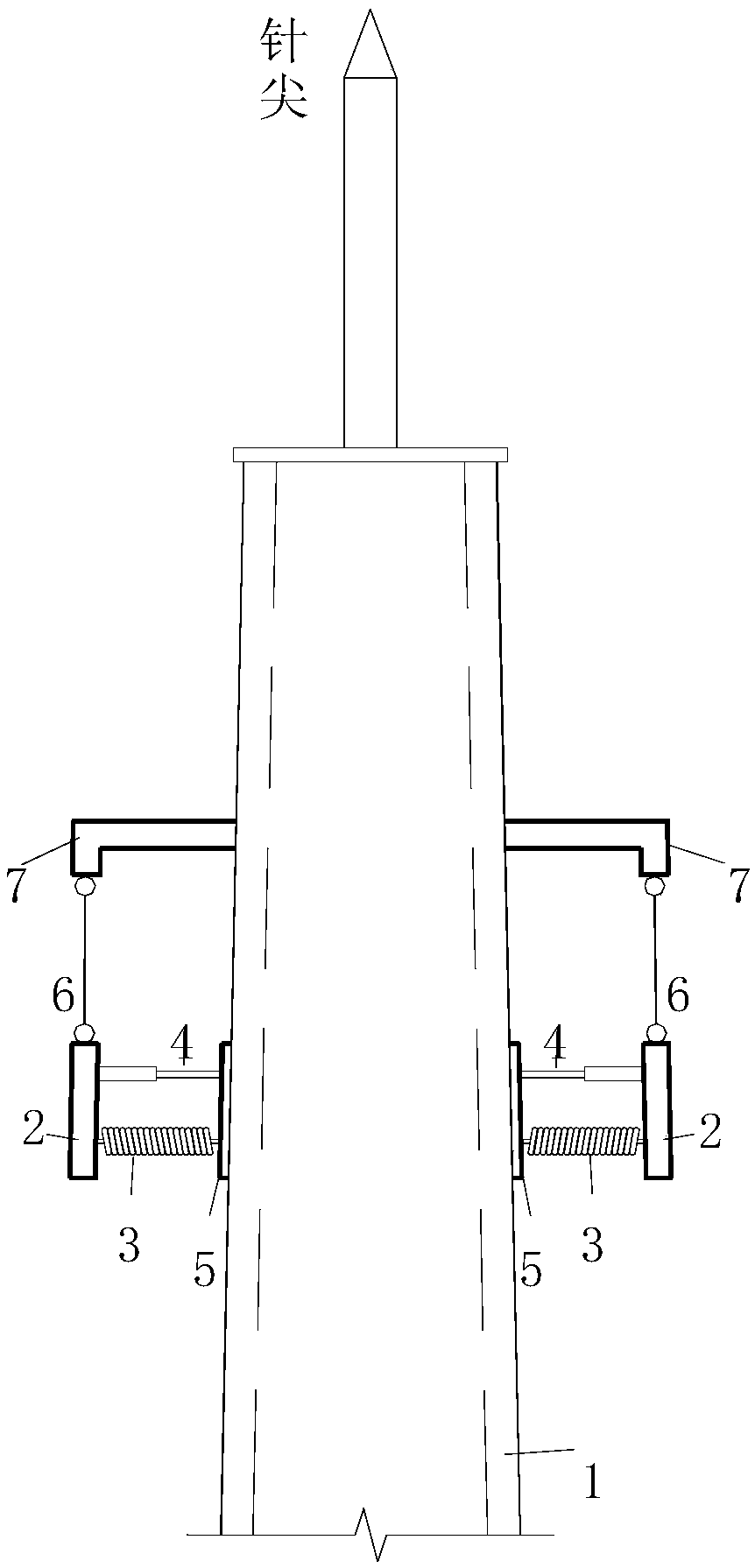
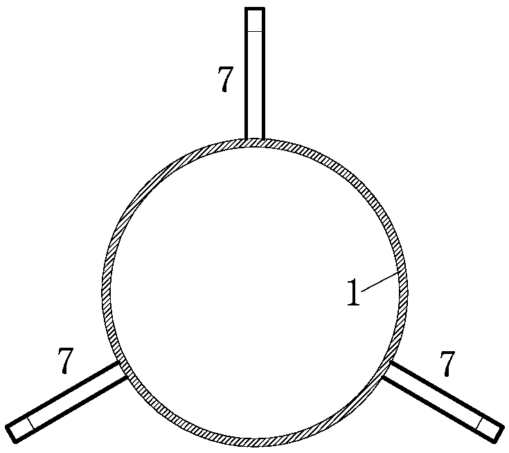
[0016] see Figure 1-5 , the substation lightning rod vibration damping device of the present invention includes a hoop 5 that is sleeved on the outer wall surface of the top of the lightning rod body 1 along the circumference, the outer level of the hoop 5 is provided with an annular mass 2, and the outer wall of the hoop 5 is connected to the ring A spring 3 and a damper 4 are connected between the inner walls of the mass 2 , and a bracket 7 is fixed outwardly on the lightning rod body 1 above the hoop 5 , and the bracket 7 is connected to the upper end surface of the annular mass 2 through a suspension cable 6 . The bracket 7 adopts several support rods welded on the lightning rod body 1, and the support rods extend outward and are evenly distributed on the periphery of the lightning rod body 1. Preferably, there are three support rods, the angle between ...


PUM


Abstract

A lightning rod vibration absorbing device for a substation comprises a ring hoop circumferentially sleeving on the outer wall surface of the top of the lightning rod body, the outer horizontal sleeveof the ring hoop is provided with an annular mass block, a spring and a damper are connected between the outer wall of the ring hoop and the inner wall of the annular mass block, a bracket is fixed on the lightning rod body above the ring hoop and extends outward, and the bracket is connected with the upper end face of the annular mass block through a suspension cable. The support frame adopts aplurality of support rods welded on the lightning rod body, and the support rods extend outward and are uniformly distributed on the outer periphery of the lightning rod. The utility model has the advantages of reasonable stress, firmness and reliability, and can effectively fix the vertical height of the annular mass. The annular mass is connected with the ring hoop fixed on the lightning rod surface by spring and damper, and the resonant energy absorption is achieved by using the inertial force or active control force of the annular mass to reduce the structural response, and then the influence of wind-induced vibration is effectively reduced.

Description

technical field [0001] The invention belongs to the field of lightning rod design, and in particular relates to a vibration damping device for a lightning rod in a substation. Background technique [0002] Lightning rod, also known as lightning protection rod, is widely used in power plants and substations as a device to protect buildings or electrical equipment from lightning strikes. The principle of the lightning rod is to install a metal rod on the top of a tall building (or tower), connect a piece of metal buried in the ground with a metal wire, and use the tip of the metal rod to discharge, so that the electricity carried by the cloud layer and the electricity on the ground gradually neutralized so as not to cause an accident. The lightning rods of substations in areas with high frequency of strong winds such as Northwest my country, North China, and Northeast China are affected by the combined influence of strong wind intensity and frequency. The lightning rods are i...

Claims


Application Information

Patent Timeline
Patent Type & Authority Applications(China)
IPC IPC(8): H02G13/00
CPCH02G13/00H02G13/80
Inventor 李毅
Owner NORTHWEST ELECTRIC POWER DESIGN INST OF CHINA POWER ENG CONSULTING GROUP
Learn More