


Quick Research
Generate reliable direction feasibility study reports for your R&D in just a few steps.

Technical Q&A
Discover and master advanced knowledge NOW. Basics, ideas, possibilities, all at once.

Find Solutions
As an expert in R&D theories, this can generate solutions to your technical problems instantly.

Evaluate Feasibility
Analyze your overall solution with one click, know your potential R&D risks in advance.

Monitor Landscape
Get weekly tech updates, stay abreast of the latest tech innovations and key insights.
Quick angle adjustment and shock absorption method of a roof photovoltaic power generation mounting plate
An angle adjustment, photovoltaic power generation technology, applied in the direction of photovoltaic power generation, photovoltaic module support structure, photovoltaic modules, etc., can solve the problem of photovoltaic power generation roof inconvenient to adjust the angle, etc., to improve the utilization of solar energy, easy to adjust the angle effect.
- Summary
- Abstract
- Description
- Claims
- Application Information
AI Technical Summary
Problems solved by technology
Method used
Image

Examples
no. 2 approach
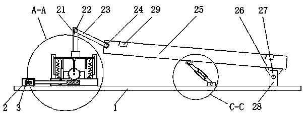
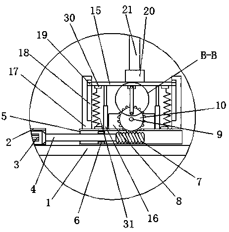
[0021] The second embodiment: a photovoltaic power generation vehicle roof, including a top cover 1, a motor casing 2 is fixedly connected to the left side of the top of the top cover 1, and a rotating motor 3 is fixedly connected to the bottom of the inner wall of the motor casing 2. The output shaft of the rotary motor 3 is fixedly connected with a rotary shaft 4, the top of the top cover 1 and the right side corresponding to the motor housing 2 are slidably connected with a fixed housing 5 through a slide rail, and the left side of the bottom of the inner wall of the fixed housing 5 is The side is fixedly connected with the limit plate 6, and the end of the rotating shaft 4 away from the rotating motor 3 passes through the fixed shell 5 and the limit plate 6 from left to right and extends to the inside of the fixed shell 5, and is located inside the solid shell 5 The right end of the rotating shaft 4 is fixedly connected with a worm 7, the top of the fixed housing 5 is fixed...
no. 3 approach
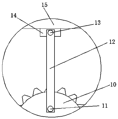
[0029] The third embodiment: a method for quick angle adjustment and shock absorption of a roof photovoltaic power generation installation plate, a worm gear transmission mechanism is installed in the vertical direction on the roof of the car as a power source, and a connecting rod is eccentrically connected to the worm gear. The connecting rod is connected to one end of the mounting plate through a rotating shaft, and the other end of the mounting plate is rotatably supported by a fixed block that can slide on the roof. The rod drives one end of the mounting plate to move upward or downward, and the rotation of the worm synchronously drives the fixed block at the bottom of the other end of the mounting plate to slide forward or backward. A nut is sleeved on the external thread, and the nut is fixedly connected with the inner ring of the bearing in the fixed block through a connecting rod, wherein the thread pattern setting direction of the external thread at the front end of t...
PUM
 Abstract
Description
Claims
Application Information
 - R&D Engineer
- R&D Manager
- IP Professional
- Industry Leading Data Capabilities
- Powerful AI technology
- Patent DNA Extraction
Browse by: Latest US Patents, China's latest patents, Technical Efficacy Thesaurus, Application Domain, Technology Topic, Popular Technical Reports.
© 2024 PatSnap. All rights reserved.Legal|Privacy policy|Modern Slavery Act Transparency Statement|Sitemap|About US| Contact US: help@patsnap.com