Welding device for incinerator manufacturing

A welding device and incinerator technology, applied in auxiliary devices, manufacturing tools, welding equipment, etc., can solve the problem of difficult manual welding operation, and achieve the effect of facilitating centralized processing, protecting the production environment, and improving work efficiency

Active Publication Date: 2018-12-14
CHONGQING SHANGZE ELECTROMECHANICAL
View PDF7 Cites 4 Cited by
  • Summary
  • Abstract
  • Description
  • Claims
  • Application Information

AI Technical Summary

Problems solved by technology

[0003] The purpose of the present invention is to provide a welding device used in the manufacture of incinerators to solve the problem of difficulty in manual welding operations, collect welding slag generated during welding, and facilitate cleaning

Method used


Image

  • Welding device for incinerator manufacturing
  • Welding device for incinerator manufacturing
  • Welding device for incinerator manufacturing

Examples


Embodiment Construction

[0017] The following is further described in detail through specific implementation methods:

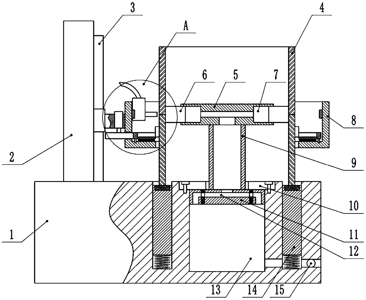
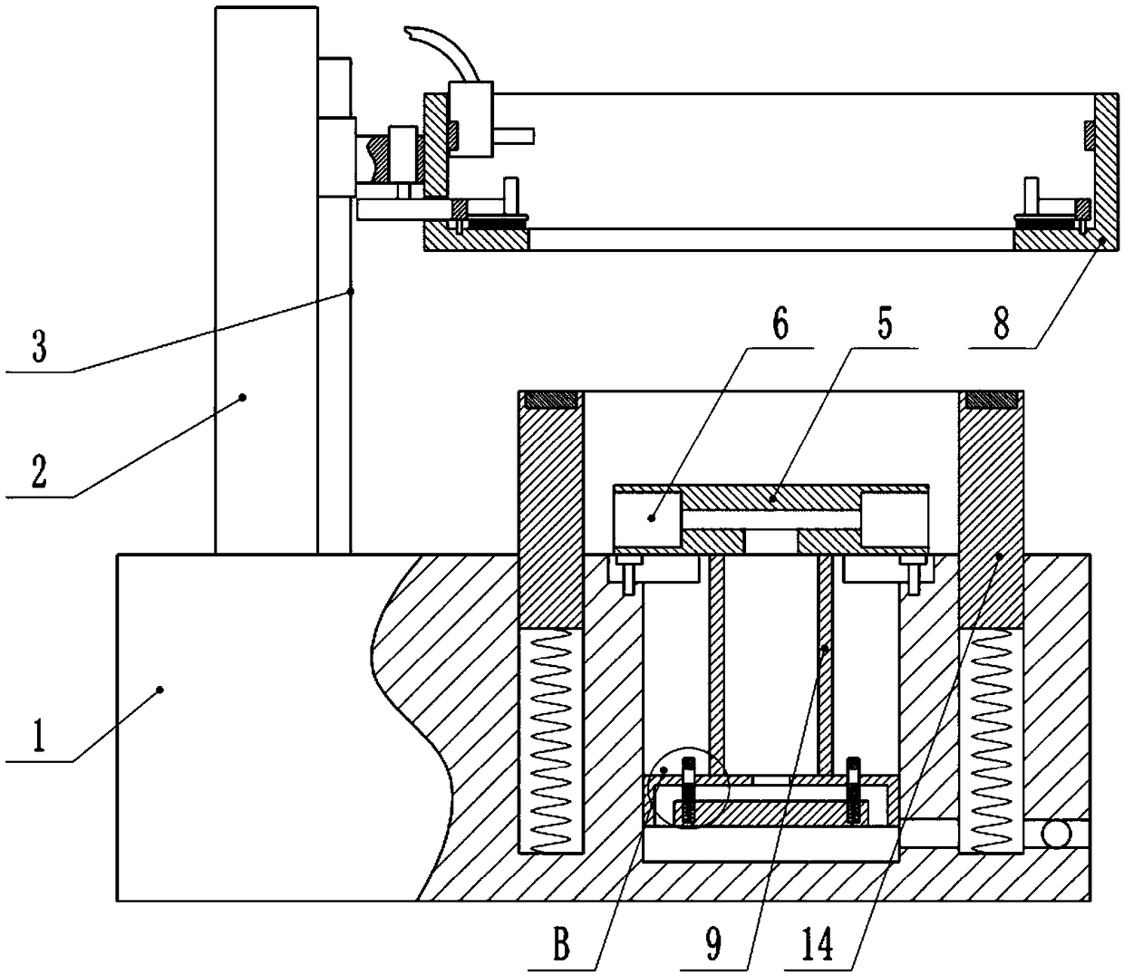
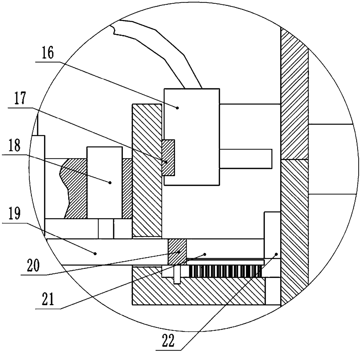
[0018] The reference signs in the drawings of the description include: base 1, support plate 2, slide rail 3, furnace body 4, baffle plate 5, positioning block 6, sliding cavity 7, slag collecting box 8, movable column 9, stop block 10, Piston 11, air channel 12, cylindrical chamber 13, annular plate 14, one-way valve 15, welding head 16, guide rail 17, servo motor 18, transmission gear 19, outer ring gear 20, electric telescopic rod 21, clamping plate 22 , plug body 23, breach 24.

[0019] The embodiment is basically as attached figure 1 , figure 2 Shown: a welding device used for incinerator manufacturing, including a base 1, and a support plate 2 integrally formed on the left side of the upper surface of the base 1. The base 1 is provided with a cylindrical cavity 13 and an annular cavity, the annular cavity and the cylindrical cavity 13 are concentrically arranged and the cyl...


PUM


Abstract

The invention belongs to the technical field of welding and particularly discloses a welding device for incinerator manufacturing. The welding device comprises a base; a supporting plate is fixedly mounted on the base; a slag collecting box is disposed on the supporting plate; a welding head is rotationally disposed in the slag collecting box; a clamping mechanism and a driving mechanism which isused for driving the clamping mechanism to rotate are disposed on the slag collecting box; a columnar cavity and an annular cavity are formed in the base; an annular plate is slideably mounted in theannular cavity; first elastic parts are arranged between the annular plate and the annular cavity; a movable body is slideably mounted in the columnar cavity; an air cavity is formed in the movable body; sliding cavities are formed in the side wall of the movable body; positioning blocks are slideably mounted in the sliding cavities; air channels which communicate with the columnar cavity are formed in the lower portion of the air cavity; plug bodies are slideably mounted on the air channels; second elastic parts are connected between the plug bodies and a movable column; notches which can communicate with the air channels are formed in the plug bodies; and stop blocks are disposed on the base. By means of the scheme, during welding, automatic alignment of two sections of a furnace body can be achieved, collection of welding slag can be achieved, and the whole working efficiency is improved.

Description

technical field [0001] The invention belongs to the technical field of welding, and in particular relates to a welding device used for incinerator manufacturing. Background technique [0002] The incinerator is a kind of harmless treatment equipment commonly used in the harmless treatment of medical and domestic waste and animals. Its principle is to use coal, fuel oil, gas and other fuels to burn and carbonize the objects to be treated at high temperature to achieve the purpose of disinfection. The furnace body of the incinerator is welded by multi-section pipe fittings. At present, the welding of the furnace body is mainly done manually. However, due to the relatively large volume of the furnace body, it is difficult to weld, difficult to operate, and difficult to ensure the quality of the weld. It is easy to cause spatter of welding slag, which may hurt the staff and pollute the working environment. Contents of the invention [0003] The object of the present inventio...

Claims


Application Information

Patent Timeline
Patent Type & Authority Applications(China)
IPC IPC(8): B23K37/02B23K37/047B23K37/08
CPCB23K37/0211B23K37/047B23K37/08
Inventor 黄云凡
Owner CHONGQING SHANGZE ELECTROMECHANICAL
Why Eureka
Try Eureka