Tobacco tar atomizer for electronic cigarettes

An oil atomizer and electronic cigarette technology, applied in the field of electronic cigarettes, can solve the problems such as the inability to change the atomization amount of e-liquid and the lack of filter structure.

Active Publication Date: 2018-12-11
深圳雷炎科技有限公司
View PDF6 Cites 0 Cited by
  • Summary
  • Abstract
  • Description
  • Claims
  • Application Information

AI Technical Summary

Problems solved by technology

However, this invention cannot change the amount of atomized smoke oil produced, and there is no filtering structure

Method used


Image

  • Tobacco tar atomizer for electronic cigarettes
  • Tobacco tar atomizer for electronic cigarettes
  • Tobacco tar atomizer for electronic cigarettes

Examples


specific Embodiment approach 1

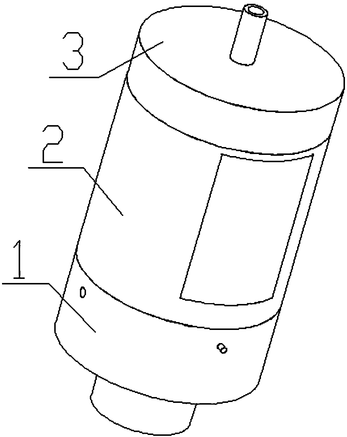
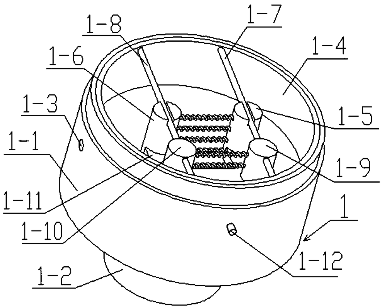
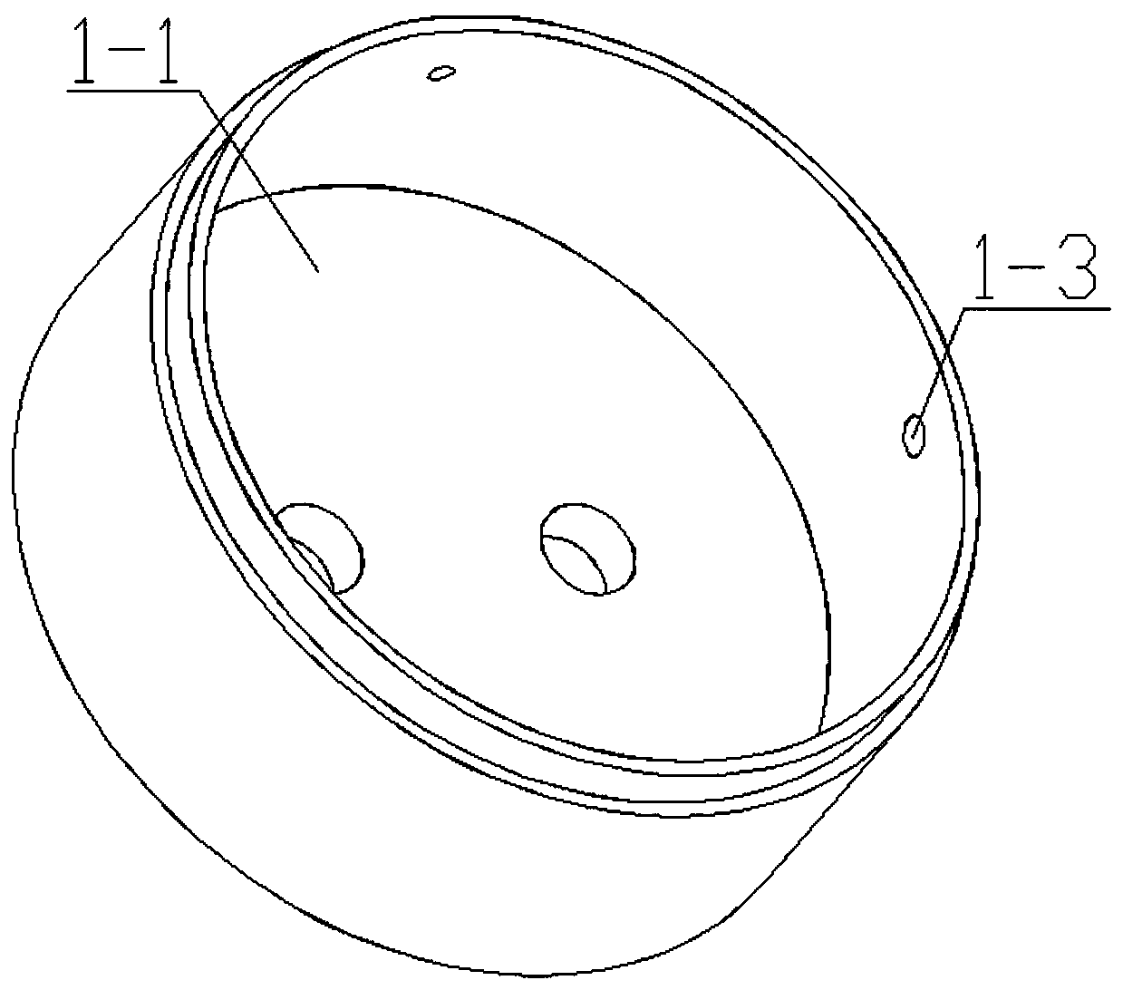
[0030] Combine below Figure 1-14 To explain this embodiment, the present invention relates to the technical field of electronic cigarettes, and more specifically, an electronic cigarette e-liquid atomizer, including an atomizing device 1, an e-liquid storage device 2 and a cigarette holder closing mechanism 3. Its beneficial effect is storage The cylinder 2-1 is filled with e-liquid, and the e-liquid falls into the ceramic atomizing core 1-4 through the multiple circular through holes on the isolation plate 2-2. At this time, the connecting guide post 1-2 is energized. The heating wire between the positive electrode 1-5 and the first negative electrode 1-6 will heat up, and the heated heating wire will heat the e-liquid and produce the e-liquid atomization gas. At this time, people can smoke the cigarette holder 3-2. While inhaling, the air will enter the device from the air inlet I1-3 and the air inlet II1-13, and the atomized gas of the e-liquid will enter people’s mouth alo...

specific Embodiment approach 2

[0034] Combine below Figure 1-14 This embodiment will be described. This embodiment will further explain the first embodiment. The first positive electrode 1-5 and the first negative electrode 1-6 are fixedly connected to the second positive electrode 1-9 and the second negative electrode 1-10. There are heating wires.

specific Embodiment approach 3

[0035] Combine below Figure 1-14 To explain this embodiment, this embodiment will further explain the first embodiment. The first limit post 1-7, the second limit post 1-8 and the push post 1-12 are all ceramic materials, and the ceramic material does not have Conductivity, the first limit post 1-7 and the second limit post 1-8 will not transfer the electricity in the first positive electrode 1-5 and the first negative electrode 1-6 to the second positive electrode 1-9 and the first The second negative pole 1-10 can also prevent people from being charged by the electricity in the push pin 1-12.


PUM


Abstract

The invention relates to the technical field of electronic cigarettes, and in particular relates to a tobacco tar atomizer for electronic cigarettes. The tobacco tar atomizer comprises an atomizationdevice, a tobacco tar storage device and a cigarette holder closing mechanism. The tobacco tar atomizer has the beneficial effects that a storage cylinder is filled with tobacco tar, the tobacco tar falls into a ceramic atomizing core through a plurality of round through holes in a separating plate, at the time, a connecting guide post is electrified, then a heating wire between a first positive electrode and a first negative electrode heats, the heating wire which heats can heat the tobacco tar, then atomized gas of the tobacco tar is generated, at the time, people can suck a cigarette holder, when sucking is carried out, air enters the device from an air inlet hole I and an air inlet hole II, the atomized gas of the tobacco tar enters the mouth of people along with the air, then the purpose of smoking is achieved, if the gas obtained after atomization seems insufficient, a push cylinder is pushed by hand, the push cylinder drives a conducting plate to move inwards, then the conducting plate is fixedly connected to a second positive electrode and a second negative electrode, and after two ends of the conducting plate contact the first positive electrode and the first negative electrode, a heating wire between the second positive electrode and the second negative electrode performs heating.

Description

Technical field [0001] The invention relates to the technical field of electronic cigarettes, and more specifically to an electronic cigarette smoke oil atomizer. Background technique [0002] Now there is an electronic cigarette with a patent number CN201420147012.2, which includes a cigarette holder cover, a cigarette holder, an atomizing tube, a battery rod, a liquid electronic cigarette liquid atomizer, a solid electronic cigarette liquid atomizer, the liquid electronic cigarette The cigarette oil atomizer and the solid electronic cigarette oil atomizer are connected side by side with the battery rod, and the atomizing tube is sleeved outside the liquid electronic cigarette oil atomizer and the solid electronic cigarette oil atomizer and connected with the battery rod , The clip of the cigarette holder is stuck between the liquid electronic cigarette oil atomizer, the solid electronic cigarette oil atomizer, and the atomizing tube, and the cigarette holder cover is covered on...

Claims


Application Information

Patent Timeline
IPC IPC(8): A24F47/00
CPCA24F47/008
Inventor 孙胜军
Owner 深圳雷炎科技有限公司
Why Eureka
Try Eureka