
New energy greenbelt spraying device

A technology of spraying device and new energy, applied in watering device, horticulture, botanical equipment and methods, etc., can solve the problems of uneven spraying and spraying unevenness, achieve uniform irrigation, improve work efficiency and quality, concept novel effect

Active Publication Date: 2018-12-07
安徽智时代科技有限公司
View PDF5 Cites 15 Cited by
  • Summary
  • Abstract
  • Description
  • Claims
  • Application Information

AI Technical Summary

Problems solved by technology

[0002] Most of the existing green space sprinkler irrigation devices use the rotation of the nozzle and the addition of a swing arm at the nozzle to increase the spraying area, but this cannot change the change of the spraying area of ​​the sprinkler. In addition, the existence of the swing arm is only sprayed by beating to a certain extent. The water column is dispersed so that the water column can be sprayed in areas with different distances. This design makes the water column spray too much water in the near area around the nozzle, and the spraying water in the distance is too small to cause uneven spraying.
[0003] Under the action of water under a certain pressure, the water column is in the shape of a parabola after spraying out. If the direction of the nozzle remains unchanged, the farthest spraying distance of the water column will not change, which will cause the unevenness of spraying. Therefore, a design is made It is very necessary to effectively change the angle of the nozzle and improve the uniformity of spraying

Method used


Image

  • New energy greenbelt spraying device
  • New energy greenbelt spraying device
  • New energy greenbelt spraying device

Examples


Embodiment Construction

[0014] The specific implementation manners of the present invention will be described in further detail below in conjunction with the accompanying drawings.

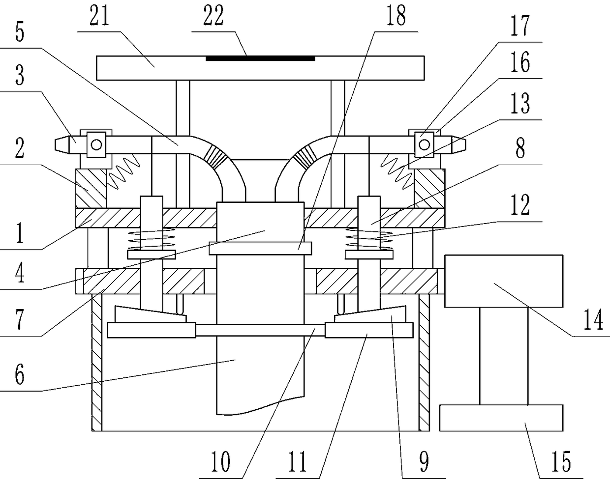
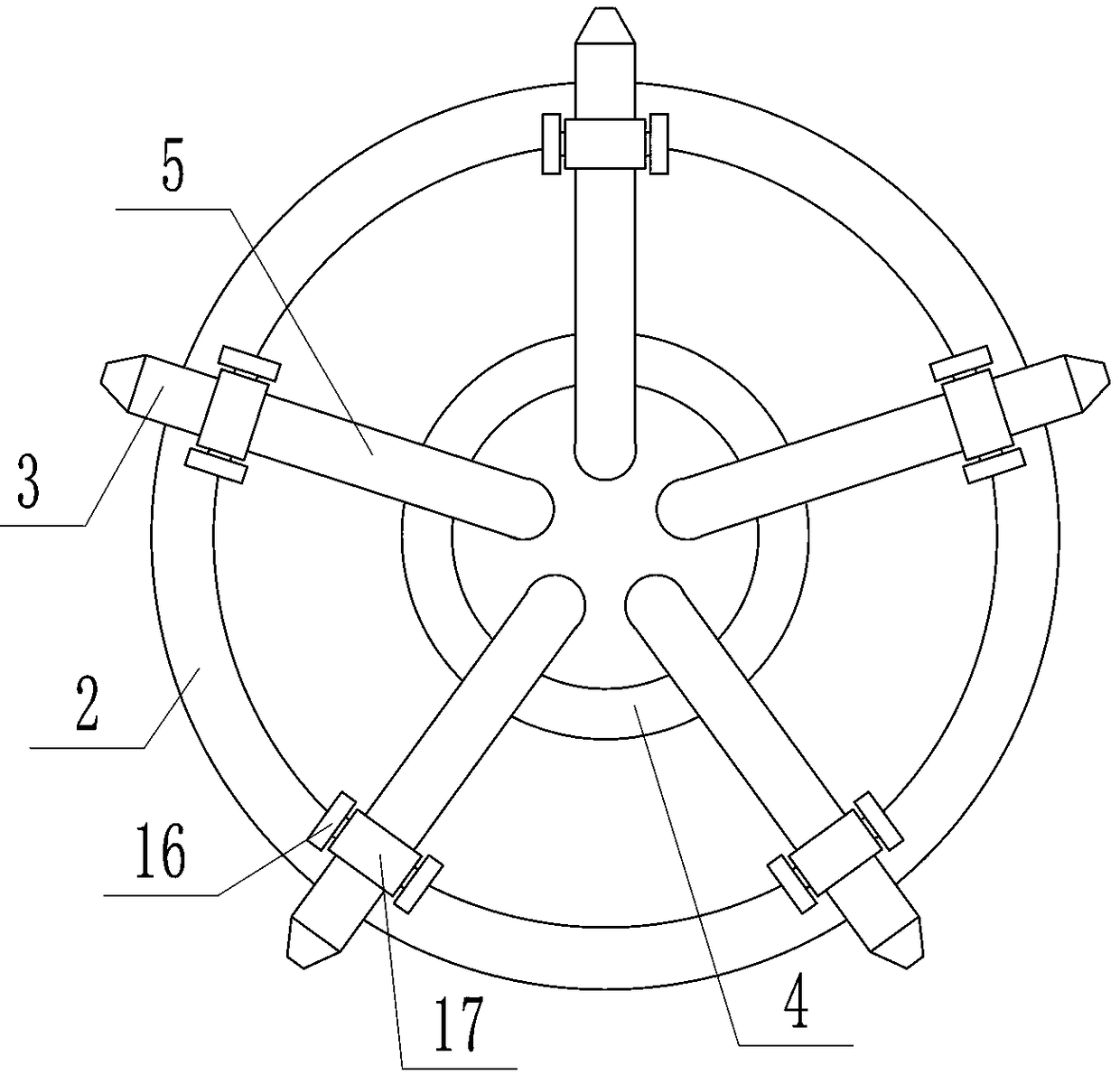
[0015] Depend on Figure 1-6 It can be seen that the present invention includes a horizontally placed and rotatable turntable 1, an annular plate 2 is provided on the upper edge of the turntable 1, and a plurality of nozzles 3 that are evenly distributed around the circumference and can rotate in a vertical plane are fixed on the upper end of the annular plate 2. , the center of the turntable 1 is fixed with a main pipe 4 which is placed vertically and can rotate with the turntable 1. The main pipe 4 is a structure with a closed upper end. A water pipe 5 is connected between each nozzle 3 and the main pipe 4. Below the main pipe 4 A water inlet pipe 6 is connected, and the main pipe 4 can rotate around the water inlet pipe 6;

[0016] The bottom of the turntable 1 is connected with a support plate 7 parallel to the turn...


PUM


Abstract

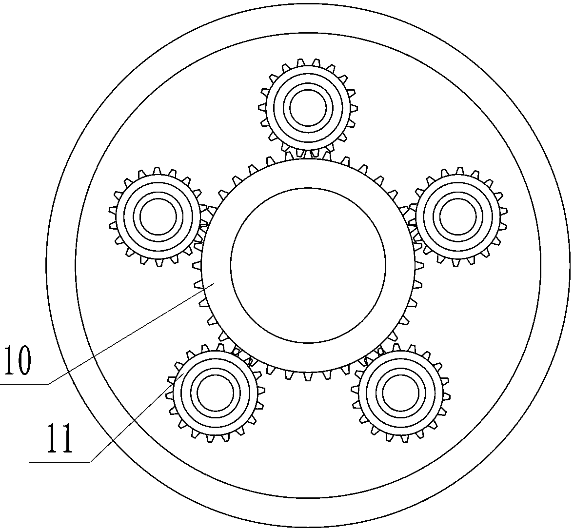
The invention discloses a new energy greenbelt spraying device. A greenbelt can be uniformly irrigated effectively, and the working efficiency and quality are improved; according to the technical scheme, the device comprises a rotating disc, nozzles are fixedly arranged on the rotating disc, a main pipeline is arranged in the center of the rotating disc, a water pipe is connected between each nozzle and the main pipeline, and a water inlet pipe is connected with the lower portion of the main pipeline; a supporting disc is connected to the lower portion of the rotating disc, a pull rod is arranged on the rotating disc, a first gear is arranged at the outer edge of the water inlet pipe, a second gear is arranged at the lower end of the pull rod, the pull rod can rotate automatically in the horizontal plane through engagement of the first gear and the second gear, a cam is arranged at the upper end face of the second gear, an ejector rod is arranged at the lower end face of the supportingdisc, an annular protrusion is arranged at the outer edge of the pull rod, a first spring is connected between the upper end of the annular protrusion and the lower end of the rotating disc, a secondspring is connected between the water pipe and the inner side wall of an annular plate, and when the pull rod is moved upwards, the nozzles can rotate reversely under the effect of the second spring.The device is novel in conception and exquisite in structure.

Description

technical field [0001] The invention relates to the technical field of green space spraying, in particular to a new energy green space spraying device. Background technique [0002] Most of the existing green space sprinkler irrigation devices use the rotation of the nozzle and the addition of a swing arm at the nozzle to increase the spraying area, but this cannot change the change of the spraying area of ​​the sprinkler. In addition, the existence of the swing arm is only sprayed by beating to a certain extent. The water column is dispersed so that the water column can be sprayed in areas with different distances. This design makes the water column spray too much water in the near area around the nozzle, and the spray water in the distance is too small to cause uneven spraying. [0003] Under the action of water under a certain pressure, the water column is in the shape of a parabola after spraying out. If the direction of the nozzle remains unchanged, the farthest sprayin...

Claims


Application Information

Patent Timeline
Patent Type & Authority Applications(China)
IPC IPC(8): A01G25/02
CPCA01G25/02
Inventor 路素青郝艳丽高晓杜林豪齐德安李喜红薛纪超刘德波
Owner 安徽智时代科技有限公司
Learn More