
Multi-pole engine array system and loudspeaker

A loudspeaker and engine technology, which is applied to loudspeakers, sensors, sensor types, etc., can solve problems such as phase distortion and harmonic distortion, and achieve the effects of improving power and efficiency, reducing group delay, and responding quickly

Pending Publication Date: 2018-11-30
张永春
View PDF5 Cites 5 Cited by
  • Summary
  • Abstract
  • Description
  • Claims
  • Application Information

AI Technical Summary

Problems solved by technology

However, due to its special diaphragm fold structure, it does not directly radiate sound waves to the front, but laterally squeezes and ejects airflow to radiate sound waves. In addition, sound waves are in a state of lateral extrusion and collision, which will cause phase distortion when sound waves of the same wavelength collide, and harmonic distortion will occur when high-order harmonics of integer multiples collide

Method used


Image

  • Multi-pole engine array system and loudspeaker
  • Multi-pole engine array system and loudspeaker
  • Multi-pole engine array system and loudspeaker

Examples


Embodiment Construction

[0046] Exemplary embodiments of the present disclosure will be described in more detail below with reference to the accompanying drawings. Although exemplary embodiments of the present disclosure are shown in the drawings, it should be understood that the present disclosure may be embodied in various forms and should not be limited by the embodiments set forth herein. Rather, these embodiments are provided for more thorough understanding of the present disclosure and to fully convey the scope of the present disclosure to those skilled in the art.

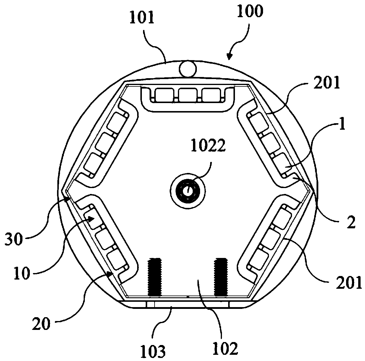
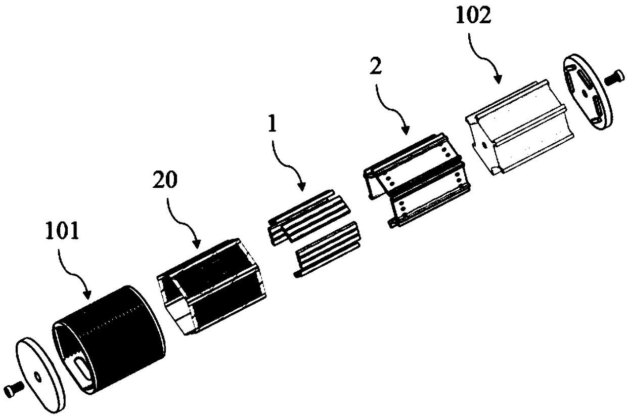
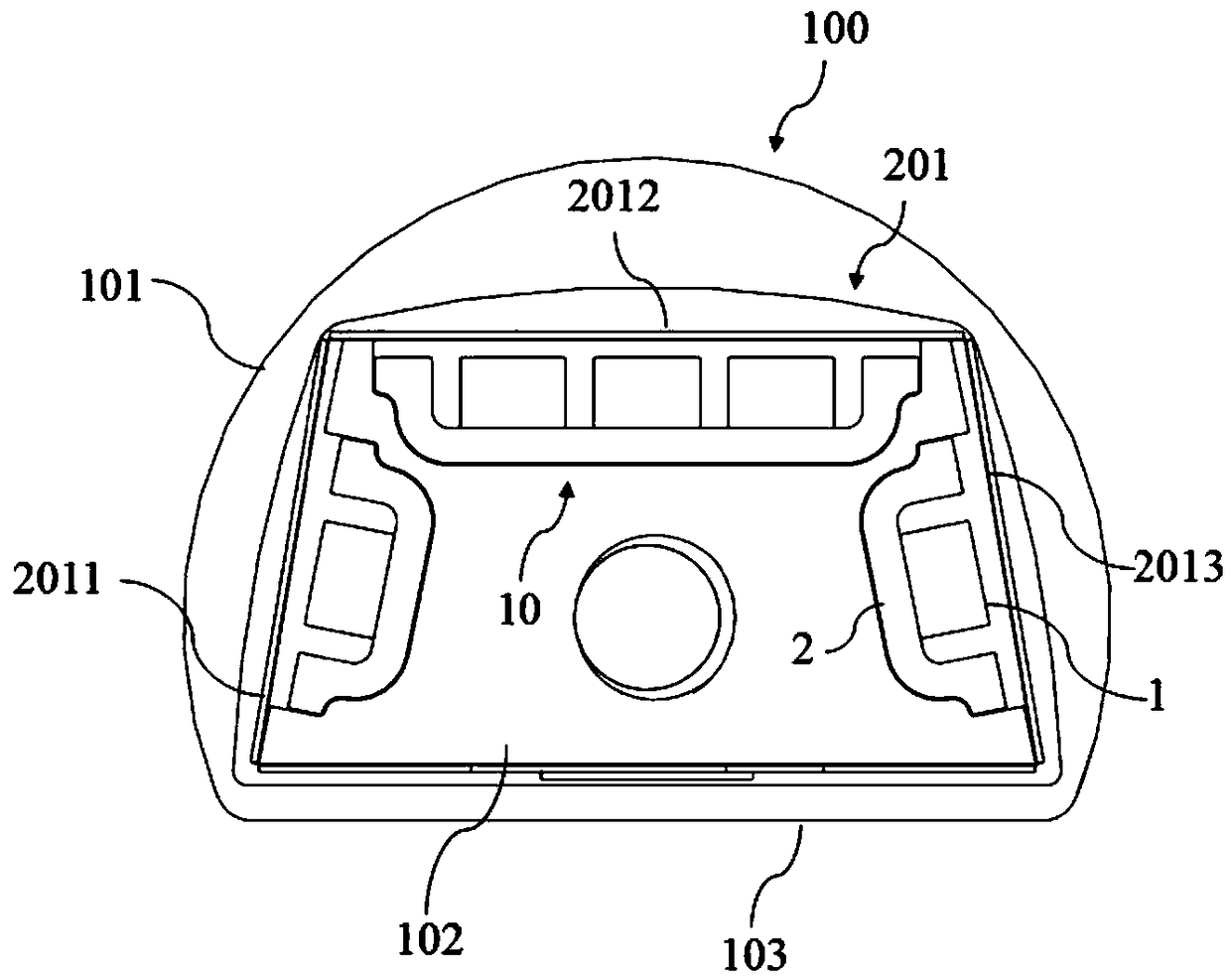
[0047] Figure 1 to Figure 8 A schematic structural diagram of a multipole engine array system provided according to an embodiment of the present invention is shown. Such as Figure 1 to Figure 8As shown, the multipole engine array system provided by the present invention is applied to a cylindrical speaker 100, including a plurality of concentrically arranged engine assemblies 10 distributed in a circular array, and a plurality o...


PUM


Abstract

The present invention provides a multi-pole engine array system and a loudspeaker. The multi-pole engine array system comprises a plurality of engine assemblies distributed in an annular array, wherein the plurality of the engine assemblies are fixed inside the annular loudspeaker through a mounting seat arranged in a casing of the annular loudspeaker; each engine component comprises a magnet conductive plate and a magnet body arranged in the magnet conductive plate; a magnetic field is formed between the magnet body and the magnet conductive plate; and the plurality of engine components are arrayed coaxially and annularly along the periphery of the mounting seat to form a multi-pole magnetic field having a plurality of magnetic pole directions. According to the multi-pole engine array system and the loudspeaker in the invention, a multi-pole magnetic field surrounded by a plane is formed via a monopole equal-magnetic-plane magnetic field through a multi-pole manner so that each pole surface of an inductive diaphragm radiates sound waves with controllable power to any configurable angular space at different angles; the diaphragms are driven to vibrate at the same time to form moreaudio information, thereby improving the power and efficiency of the loudspeaker; and the reaction speed is faster.

Description

technical field [0001] The invention relates to the technical field of electric loudspeakers, in particular to a multi-pole engine array system and a loudspeaker. Background technique [0002] Traditional mid-range and high-pitched speaker units generally include cone speakers, dome speakers, horn speakers, ribbon speakers, flat speakers, etc. Among them, the wave front of the radiation wave of the cone speaker, the dome speaker, and the horn speaker belongs to the spherical wave. The wave front of the spherical wave changes sharply from the center to the edge, and the driving force generated by the voice coil is not flat on the diaphragm. , but it is first transmitted to the edge of the diaphragm (individual midrange speakers are the center of the diaphragm), and then gradually transmitted to other parts of the entire diaphragm, which will inevitably take a certain amount of time. Therefore, at a certain moment, the force on each part of the diaphragm will be uneven, and i...

Claims


Application Information

Patent Timeline
Patent Type & Authority Applications(China)
IPC IPC(8): H04R9/06H04R9/02
CPCH04R9/02H04R9/06H04R2400/11H04R9/063H04R1/403H04R7/122H04R9/025H04R2209/022H04R1/02
Inventor 张永春
Owner 张永春
Learn More