Quantitative analysis method of temperature distribution of gis equipment shell

A technology of quantitative analysis and shell temperature, applied in the directions of temperature distribution map, radiation pyrometry, measuring device, etc., can solve the problems of difficult heat dissipation, gas decomposition, abnormal thermal image of equipment, etc., and achieve the effect of improving the accuracy of on-site detection

Inactive Publication Date: 2020-06-19
ELECTRIC POWER RESEARCH INSTITUTE OF STATE GRID NINGXIA ELECTRIC POWER COMPANY +1
View PDF3 Cites 0 Cited by
  • Summary
  • Abstract
  • Description
  • Claims
  • Application Information

AI Technical Summary

Problems solved by technology

When a local hot spot appears on the GIS equipment, it will cause abnormalities in the thermal image of the equipment, and the temperature of the specific hot spot may exceed the ambient temperature by more than 40 degrees
[0003] Since the interior of GIS equipment is a closed space, once local hot spots appear inside, the heat is not easy to dissipate, which can easily lead to continuous rise in temperature, and even gas decomposition, which will endanger the insulation performance
However, when local hot spots appear on the shell, it indicates that eddy current loss occurs, which will lead to serious loss of metal properties of the equipment.
At present, infrared imagers are mostly used to measure the temperature of GIS equipment, and the thermal image measured by the infrared imager is only a reflection of the temperature of the equipment shell, and it is impossible to detect the temperature distribution inside the equipment. Therefore, it is impossible to judge the heat source from the thermal image alone. On the surface of the device or inside the device

Method used


Image

  • Quantitative analysis method of temperature distribution of gis equipment shell
  • Quantitative analysis method of temperature distribution of gis equipment shell
  • Quantitative analysis method of temperature distribution of gis equipment shell

Examples


Embodiment Construction

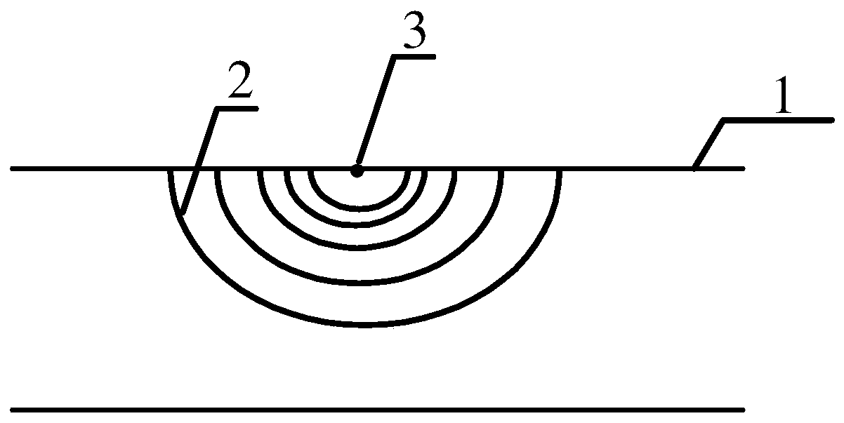
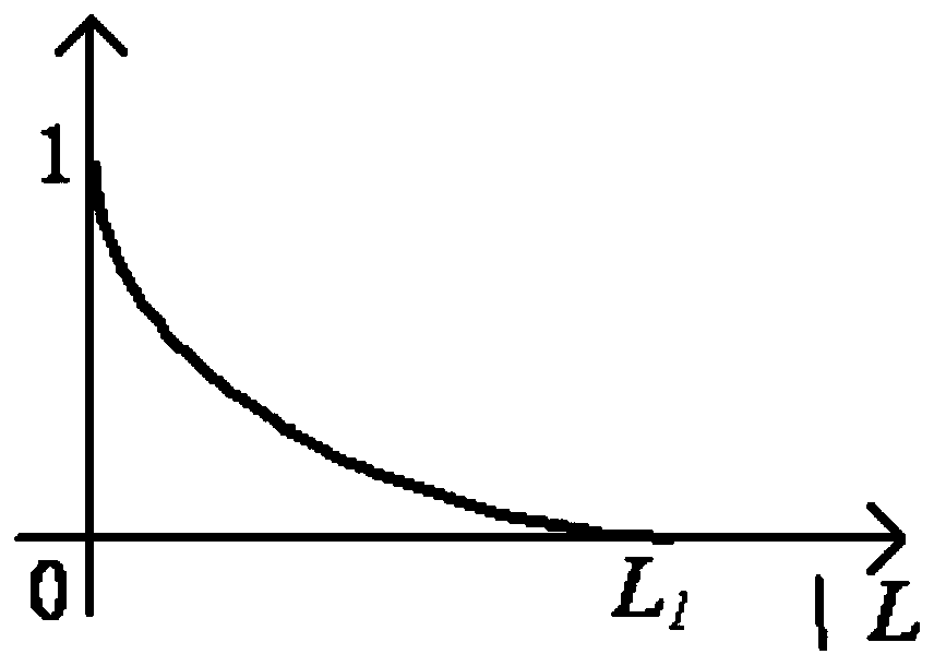
[0016] The invention relates to a quantitative analysis method for the temperature distribution of the shell of GIS equipment. Specifically, an infrared imager is used to measure the surface temperature of the shell of the GIS equipment, and the temperature distribution map obtained is extracted from the temperature distribution map, and the isotherm is drawn, and then obtained. Temperature gradient curve, normalize the temperature gradient curve, calculate its equivalent area percentage, analyze the shell temperature of the GIS equipment according to the equivalent area percentage, and then judge whether the heat source comes from the inside of the GIS or the shell surface.

[0017] In order to facilitate those skilled in the art to understand the present invention, the present invention will be further described according to the accompanying drawings.

[0018] Step (1): Measure the temperature distribution of the shell of the tested GIS equipment to obtain its infrared therma...


PUM


Abstract

The invention relates to a quantitative analysis method for the temperature distribution of a GIS equipment shell. Its characteristic is that it includes the following steps: (1) measure the temperature distribution of the tested GIS equipment casing to obtain an infrared thermal image; (2) calculate the temperature distribution according to the infrared thermal image, and extract the distance and position of the heating point Several temperature values ​​draw isotherms; (3) draw distance-temperature gradient curves according to isotherms, and carry out normalization; (4) calculate the equivalent area percentage of distance-temperature gradient curves after normalization; ( 5) Quantitative analysis of the temperature distribution is carried out according to the obtained equivalent area percentage, so as to determine whether the heat source comes from the inside of the device or on the surface of the device shell. It has been proved by trial that after adopting the method of the present invention, further quantitative analysis can be carried out on the infrared thermal image, and the characteristic parameters can be extracted, and then the position of the heat source can be accurately judged, so as to improve the accuracy of on-site detection.

Description

technical field [0001] The invention relates to a quantitative analysis method for the temperature distribution of a GIS equipment shell. Background technique [0002] Large power transformers and gas-insulated metal-enclosed switchgear (GIS) are the most important equipment in the current power system, and their operational reliability is directly related to the safety and stability of the power grid system. During the operation of GIS equipment, local hot spots will appear, which will lead to abnormal heating. The main causes of local hot spots are local hot spots in the shell caused by eddy currents, internal local hot spots due to poor contact of internal high-voltage conductors, etc. When a local hot spot appears on the GIS equipment, it will cause abnormalities in the thermal image of the equipment, and the temperature of the specific hot spot may exceed the ambient temperature by more than 40 degrees. [0003] Since the interior of the GIS equipment is a confined sp...

Claims


Application Information

Patent Timeline
Patent Type & Authority Patents(China)
IPC IPC(8): G01J5/00
CPCG01J5/00G01J5/0096G01J2005/0077G01J5/485
Inventor 马波吴旭涛李秀广闫振华丁培刘世涛郝金鹏倪辉周秀马云龙魏莹
Owner ELECTRIC POWER RESEARCH INSTITUTE OF STATE GRID NINGXIA ELECTRIC POWER COMPANY
Why Eureka
Try Eureka