Improved connector

A connector and mating connection technology, applied in the direction of connection, parts of the connection device, device for joining/disconnecting the connection parts, etc., can solve the problems of easy electric shock accidents, high risk of use, unstable use, etc., to achieve Easy to power on and off, easy to automatically lock, and prevent accidental power off

Inactive Publication Date: 2018-11-27
广州普隆智能设备有限公司
View PDF2 Cites 6 Cited by
  • Summary
  • Abstract
  • Description
  • Claims
  • Application Information

AI Technical Summary

Problems solved by technology

[0002] When the electrical equipment is powered on, it needs to use a connector to connect the mains power to the electrical equipment. At present, when the electrical equipment is connected to the electricity, the connector on the electrical equipment and the socket are connected by friction fit. When accidentally touching When connecting to the connector on the electrical equipment, it is prone to accidental power failure, and the use is unstable. Moreover, the socket is always in the energized state. When plugged in, it is easy to cause electric shock accidents, and the risk factor is high. Therefore, it needs to be improved.

Method used


Image

  • Improved connector
  • Improved connector
  • Improved connector

Examples


Embodiment Construction

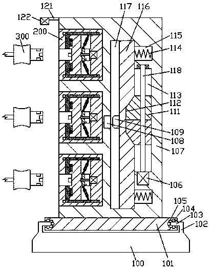
[0016] Combine below Figure 1-3 The present invention will be described in detail.

[0017] refer to Figure 1-3 , an improved connector according to an embodiment of the present invention, comprising a chassis 100, a steering wheel 101 mounted on the chassis 100 in rotation, a main seat body 107 fixedly mounted on the steering wheel 101, and The connecting head 300 is locked and connected with the main base body 107. The left end surface of the main base body 107 is provided with a multi-assembly insert 200, and the left end surface of the installation base 200 is provided with an insertion cavity 214. The inner wall on the right side of the inserting cavity 214 is fixed with a first coupling head 215, and the upper and lower inner walls of the inserting cavity 214 are symmetrically provided with a first sliding cavity 216, and an oblique shape is slidably fitted in the first sliding cavity 216. The locking block 217, the second sliding cavity 212 is provided in the inner ...


PUM


Abstract

The invention discloses an improved connector. The improved connector comprises a bottom frame, a steering wheel which is mounted on the bottom frame in a rotary match manner, a main seat body which is fixedly mounted on the steering wheel and a connector which is connected with the main seat body in a locking match manner; a plurality of groups of embedding seats are arranged in a left-side end face of the main seat body; inserting and fixing cavities are formed in the left-end side faces of the embedding seats; a first electrifying head is fixedly arranged on a right-side inner wall of eachinserting and fixing cavity; first sliding cavities are symmetrically arranged in upper and inner walls of the inserting and fixing cavities; inclined locking blocks are mounted in the first sliding cavities in a sliding match manner; second sliding cavities are arranged in the right-side inner walls of the first sliding cavities; first sliding blocks are mounted in the second sliding cavities inthe sliding match manner; jacking springs are mounted in the second sliding cavities in one side relative to the first sliding blocks at the upper and lower sides in a jacking match manner.

Description

technical field [0001] The invention relates to the technical field of connectors, in particular to an improved connector. Background technique [0002] When the electrical equipment is powered on, it is necessary to use a connector to connect the mains power to the electrical equipment. At present, when the electrical equipment is connected to the electricity, the connector on the electrical equipment and the socket are connected by friction fit. When connecting to the connector on the electrical equipment, accidental power failure is likely to occur, and the use is unstable. Moreover, the socket is always in a energized state. When plugged in, electric shock accidents are likely to occur, and the risk factor is high. Therefore, improvement is needed. Contents of the invention [0003] The object of the present invention is to provide an improved connector for overcoming the above-mentioned defects in the prior art. [0004] An improved connector according to the present...

Claims


Application Information

Patent Timeline
IPC IPC(8): H01R13/44H01R13/502H01R13/622H01R13/627H01R13/629H01R13/703H01R13/713
CPCH01R13/6275H01R13/44H01R13/502H01R13/622H01R13/629H01R13/7035H01R13/713
Inventor 胡将龙
Owner 广州普隆智能设备有限公司
Why Eureka
Try Eureka