Adjustable cable clamp positioning device
A positioning device, an adjustable technology, applied in the direction of electrical components, etc., can solve the problems of inapplicability, fixing and clamping cables, falling off at both ends of the fixed structure, etc.
- Summary
- Abstract
- Description
- Claims
- Application Information
AI Technical Summary
Problems solved by technology
Method used
Image
Examples
Embodiment 1
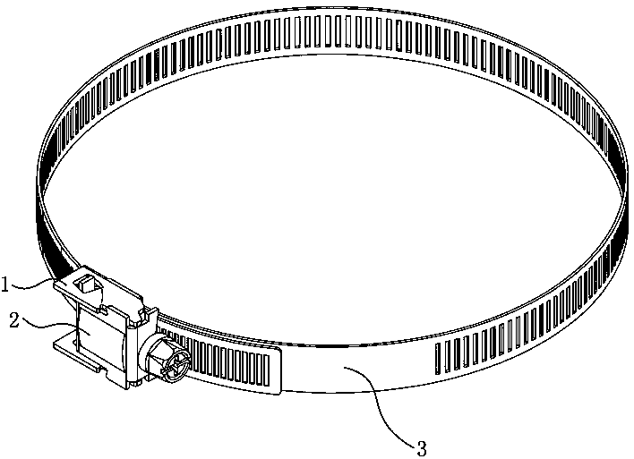
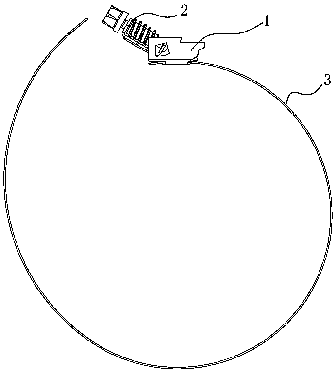
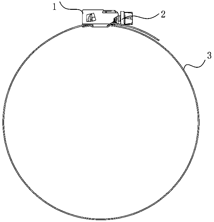
[0024] Embodiment 1: An adjustable wire clamp positioning device, including a wire clamp adjustment unit 1 and a cable fixing unit 3, the cable fixing unit 3 is snapped to the inner end of the wire clamp adjustment unit 1, the The clamp adjustment unit 1 includes a fixed base 101, a positioning clip 102 and a support block 103, the two ends of the fixed base 101 are provided with a positioning clip 102, and the two sides of the fixed base 101 are provided with a support block 103 , the support block 103 is provided with a relief slot 104, the cable fixing unit 3 is a bendable structure, and the cable fixing unit 3 includes a band 301, a fixing bayonet 302 and a limit variable A diameter interface 303, one end of the band 301 is provided with a fixed bayonet 302, the fixed bayonet 302 is engaged with the positioning clip 102, and one side of the fixed bayonet 302 is provided with a limited variable diameter interface 303, the The positioning clamp 102 at the other end of the fi...
Embodiment 2
[0025] Embodiment 2: An adjustable wire clamp positioning device, including a wire clamp adjustment and abdication unit 1, a positioning locking unit 2, and a cable fixing unit 3, and the two sides of the positioning and locking unit 2 are clamped to the wire clamp Adjust the inside of the step-off unit 1 and connect it in an overturned fixed manner. The positioning and locking unit 2 includes a positioning seat 201, a limiting clip 202, a fixing clip 203 and a fixing clip 204. One end of the positioning seat 201 is provided with a limiting Clamp 202, the other end of the positioning seat 201 is provided with a fixed clamp 203, the limit clamp 202 is provided with a deformed bayonet 205, and the front end of the fixed clamp 204 is crimped in the deformed bayonet 205, so The two ends of the fixed clamping plate 203 are clamped in the give way slot 104, the fixed clamping plate 203 is provided with a through hole 206, and the other end of the fixed clamping member 204 penetrates ...
Embodiment 3
[0026] Embodiment 3: The side end of the connection between the fixed base 101 and the support block 103 is provided with a relief groove 105, the support block 103 is a special-shaped structure, and the upper end of the support block 103 is provided with a corner groove 106, so that The side end of the support block 103 is provided with an arc-shaped curved groove 107, and the two sides of the positioning seat 201 are provided with protrusions 208, and the protrusions 208 are matched with the corner grooves 106. The side end of the plate 202 is provided with an extension protrusion 209, and the extension protrusion 209 is adapted to the arc-shaped curved groove 107, and the fixed clamping plate 203 is provided with a special-shaped protrusion 210, and the special-shaped protrusion 210 is compatible with the abdication The groove portion 105 is adapted, and the rest of the technical solutions are the same as those in the first and second embodiments.
PUM
 Abstract
Description
Claims
Application Information
 - Generate Ideas
- Intellectual Property
- Life Sciences
- Materials
- Tech Scout
- Unparalleled Data Quality
- Higher Quality Content
- 60% Fewer Hallucinations
Browse by: Latest US Patents, China's latest patents, Technical Efficacy Thesaurus, Application Domain, Technology Topic, Popular Technical Reports.
© 2025 PatSnap. All rights reserved.Legal|Privacy policy|Modern Slavery Act Transparency Statement|Sitemap|About US| Contact US: help@patsnap.com


