
Tire

A tire and tire circumferential technology, applied to tire parts, tire tread/tread pattern, transportation and packaging, etc., can solve the problems of reduced rigidity of the land part, reduced handling stability on dry roads, and reduced ground contact area, etc. To achieve the effect of suppressing the significant reduction and suppressing the handling stability performance

Active Publication Date: 2018-11-23
SUMITOMO RUBBER IND LTD
View PDF23 Cites 0 Cited by
  • Summary
  • Abstract
  • Description
  • Claims
  • Application Information

AI Technical Summary

Problems solved by technology

However, if the groove volume is increased, the ground contact area will be reduced, the rigidity of the land portion will be reduced, and there will be problems such as a reduction in steering stability on dry roads.

Method used


Image

  • Tire
  • Tire
  • Tire

Examples


Embodiment

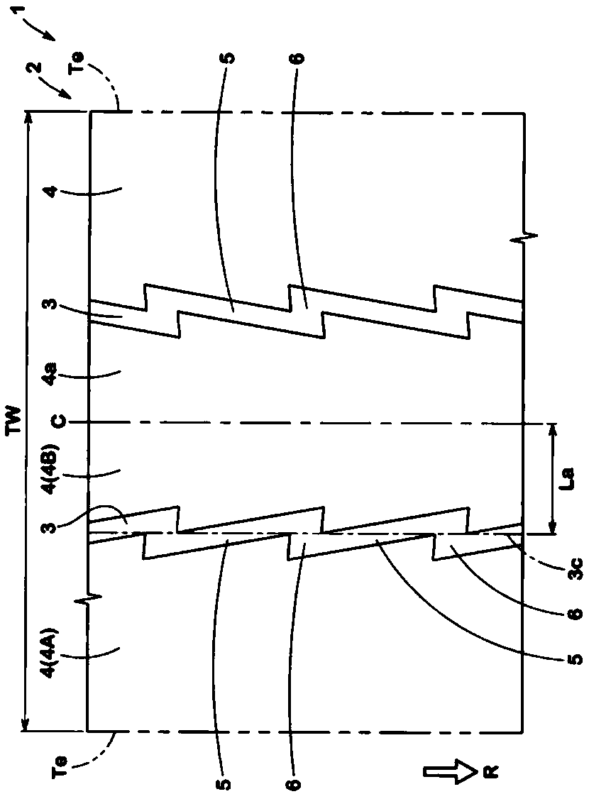
[0065] Based on the specifications in Table 1, prototypes with figure 1 The pneumatic tires with the size of 245 / 40R18 in the basic pattern were tested for the handling stability and drainage performance of each trial tire. The main common specifications and test methods of each trial tire are as follows.

[0066] Groove depth of the main groove (inclined elements and axial elements): 6mm.

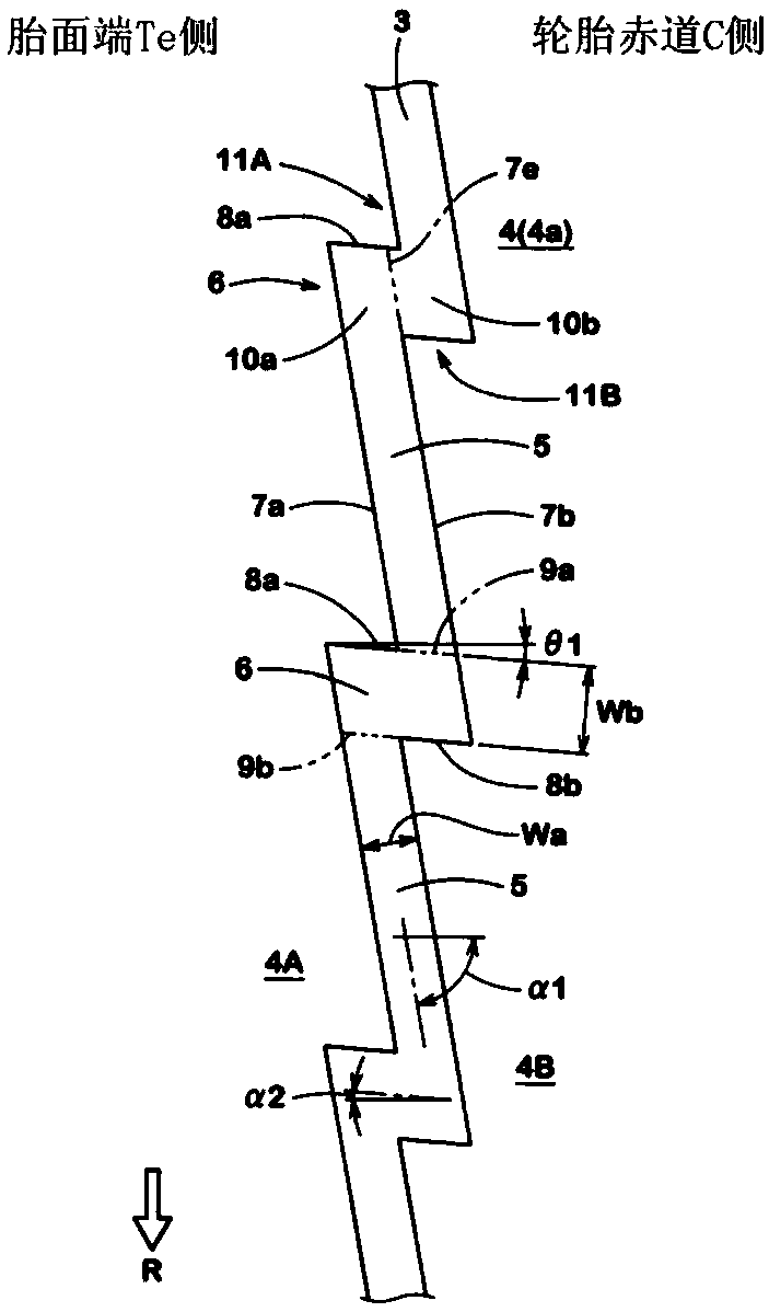
[0067] The maximum width Wa of the inclined element: 10mm (3.2% of the tread width)

[0068] Angle θ1 of the inclined element: 80°.

[0069] "Parallel to the trench wall of the rear grounding side" in Table 1 means that the edge of the trench wall of the first grounding side extends parallel to the edge of the trench wall of the rear grounding side.

[0070] "Opposite to the rear ground contact side groove wall" in Table 1 means that the bezel of the ground contact first side groove wall is inclined toward the rear ground contact side in the rotation direction R toward the tire equator ...


PUM


Abstract

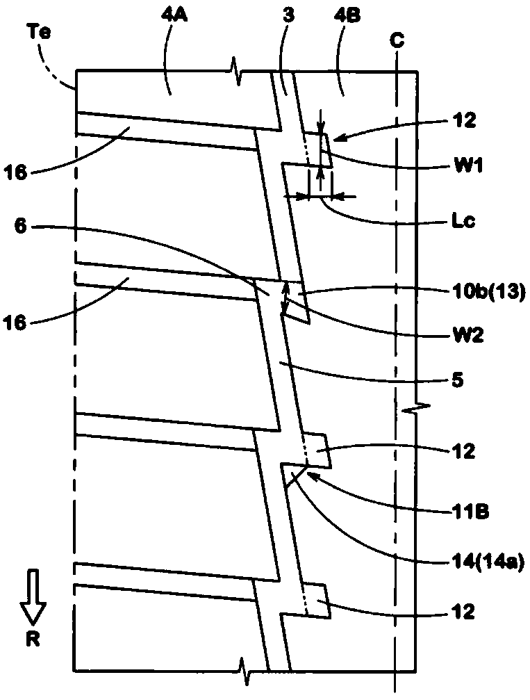
The invention provides a tire. The steering stability degradation of the tire is inhibited, and the drainage performance is improved. The rotation direction (R) of the tire (1) is designated. The tread (2) is provided with a main groove (3) that extends in a zigzag shape. The main groove (3) alternatively comprises inclined elements (5) and axial elements (6) along the circumferential direction ofthe tire. The inclined elements (5) obliquely extend to external side of the tire facing the rotation direction (R), the axial elements (6) extend along the axial direction of the tire from the rotation direction (R), and thus the trench wall (8a) of the grounding side in the rotation direction (R) arranged on the external part in the axial direction of the tire can scratch water in front of thetire during the driving process. The maximal width (Wb) of the axial elements (6) is greater than the maximal width (Wa) of the inclined elements (5).

Description

technical field [0001] The present invention relates to a tire provided with main grooves extending continuously in a zigzag shape on a tread portion. Background technique [0002] Conventionally, it is known that the overall width and depth of the main groove are increased to increase the groove volume in order to improve the drainage performance of the tire. However, if the groove volume is increased, the contact area decreases, the rigidity of the land portion decreases, and there is a problem that the steering stability performance on a dry road surface decreases. [0003] In particular, in tires for racing cars that run at high speeds and under high loads, in order to generate a large cornering force, it is desired to ensure the rigidity of the land portion and improve drainage performance. [0004] Patent Document 1: Japanese Patent Laid-Open No. 2016-97779 Contents of the invention [0005] The present invention has been made in view of the above circumstances, an...

Claims


Application Information

Patent Timeline
IPC IPC(8): B60C11/03B60C11/12
CPCB60C11/0323B60C11/1259B60C11/1272B60C2011/1286B60C2011/1268B60C11/04B60C11/0306B60C2011/0388B60C11/0302B60C2011/0346B60C11/03B60C11/12B60C11/13B60C2011/0381
Inventor 石桥隆志
Owner SUMITOMO RUBBER IND LTD
Learn More