
Stapler device and application method thereof

A stapler and staple technology, applied in the direction of nailing U-shaped nail tools, nailing tools, manufacturing tools, etc., can solve the problems of reducing the scope of application, poor safety, inconvenient use, etc.

Inactive Publication Date: 2018-11-23
朱晓燕
View PDF0 Cites 2 Cited by
  • Summary
  • Abstract
  • Description
  • Claims
  • Application Information

AI Technical Summary

Problems solved by technology

[0002] The stapler is an ideal means for us to bind many pages of paper together for preservation. The manual stapler is an important auxiliary equipment for office and study. It is mainly carried out by pressing. And it is widely used, and because the traditional stapler often manually toggles the elastic pressure plate when loading the staples, and in the process of operation, one hand operates the elastic pressure plate, and the other hand loads the staples, thus , it is very inconvenient to use, and in the process of operation, it is easy to scratch the hand if you are not careful, and its safety is poor. However, the length of the legs of the staples that can be bound by the traditional stapler is limited, thus encountering To bind thicker documents, it is necessary to replace a large stapler, thereby reducing the scope of application

Method used


Image

  • Stapler device and application method thereof
  • Stapler device and application method thereof

Examples


Embodiment Construction

[0020] All features disclosed in this specification, or steps in all methods or processes disclosed, may be combined in any manner, except for mutually exclusive features and / or steps.

[0021] Any feature disclosed in this specification, unless specifically stated, can be replaced by other alternative features that are equivalent or have similar purposes. That is, unless expressly stated otherwise, each feature is one example only of a series of equivalent or similar features.

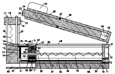
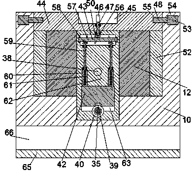
[0022] Such as Figure 1-2As shown, a stapler device of the device of the present invention includes a base body 10, and the base body 10 is provided with a placement chamber 11 with an opening facing upwards and used for placing staples 13, and the placement chamber 11 is fixedly installed with Fixed block 12, the fixed block 12 is provided with a first sliding groove 34 with an opening facing right and communicating up and down, the right end surface of the fixed block 12 is fixedly connected with ...


PUM


Abstract

The invention discloses a stapler device. The stapler device comprises a base body, the base body is provided with a containing cavity provided with an upward opening and used for containing a staple,a fixing block is fixedly arranged in the containing cavity and is provided with a first sliding groove with a rightward opening and penetrating through up and down, the right end surface of the fixing block is fixedly connected to the right end wall of the containing cavity, a pressing groove is defined by the left end of the fixing block and the left end wall of the containing cavity, the leftside of the bottom wall of the containing cavity is provided with a nail outlet groove communicated with the outside and communicated with the pressing groove, a second sliding groove is defined by the front end surface and the rear end wall of the fixing block and the front end wall and the rear end wall of the containing cavity, a first sliding block is arranged in the second sliding groove in asliding mode, a second sliding block which is matched with the upper end surface of the fixing block in a sliding mode is arranged in the containing cavity, and the lower end of the second sliding block is fixedly connected to the first sliding block.

Description

technical field [0001] The invention relates to the field of office supplies, in particular to a stapler device and a using method thereof. Background technique [0002] The stapler is an ideal means for us to bind many pages of paper together for preservation. The manual stapler is an important auxiliary equipment for office and study. It is mainly carried out by pressing. And it is widely used, and because the traditional stapler often manually toggles the elastic pressure plate when loading the staples, and in the process of operation, one hand operates the elastic pressure plate, and the other hand loads the staples, thus , it is very inconvenient to use, and in the process of operation, it is easy to scratch the hand if you are not careful, and its safety is poor. However, the length of the legs of the staples that can be bound by the traditional stapler is limited, thus encountering When it comes to binding thicker documents, it is necessary to replace a large stapl...

Claims


Application Information

Patent Timeline
IPC IPC(8): B25C5/16B25C7/00
CPCB25C7/00B25C5/1686
Inventor 朱晓燕
Owner 朱晓燕
Learn More