Automatic punching and forming die for electronic component and using method

A technology for electronic components and molding dies, which is applied in the field of punching dies, and can solve problems such as inappropriate cutting of conductive iron wires

Inactive Publication Date: 2018-11-23
曹炳全
View PDF0 Cites 2 Cited by
  • Summary
  • Abstract
  • Description
  • Claims
  • Application Information

AI Technical Summary

Problems solved by technology

But this punching mold is not suitable for cutting conductive wire on electronic components

Method used


Image

  • Automatic punching and forming die for electronic component and using method
  • Automatic punching and forming die for electronic component and using method
  • Automatic punching and forming die for electronic component and using method

Examples


Embodiment Construction

[0027] The following will clearly and completely describe the technical solutions in the embodiments of the present invention with reference to the accompanying drawings in the embodiments of the present invention. Obviously, the described embodiments are only some, not all, embodiments of the present invention. Based on the embodiments of the present invention, all other embodiments obtained by persons of ordinary skill in the art without making creative efforts belong to the protection scope of the present invention.

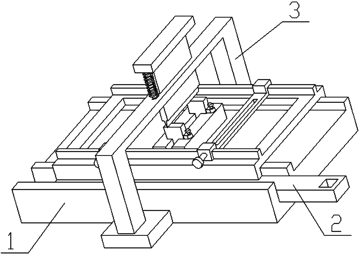
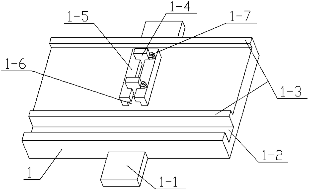
[0028] see Figure 1-5 , the invention provides a technical solution: an automatic punching molding die for electronic components, including a base 1, a sliding frame assembly 2 and a punching assembly 3, the base 1 is provided with a protruding plate 1-1, a grip Rod chute 1-2, convex rib I1-3, splint 1-4, placing table 1-5, T-shaped chute 1-6 and fastening screw I1-7, the front end and the rear end of the base 1 are in the middle The positions are fixedly co...


PUM


Abstract

The invention discloses an automatic punching and forming die for an electronic component. The automatic punching and forming die comprises a base, a sliding frame assembly and a punching assembly, the base is provided with protruding plates, a hand grabbing rod sliding groove, convex edges I, clamping plates, a placing table, a T-shaped sliding groove and fastening screws I, the middle position of the front end and the middle position of the rear end of the base are fixedly connected with the protruding plates correspondingly, the two convex edges I are arranged at the upper end of the base,the front end of the base is provided with the hand grabbing rod sliding groove, the middle position of the upper end of the base is fixedly connected with the placing table, the T-shaped sliding groove is formed in the placing table, the T-shaped sliding groove is connected with the two clamping plates in a sliding mode, and the two clamping plates are connected with the fastening screws I through welding.

Description

technical field [0001] The invention relates to a punching die, in particular to an automatic punching molding die for electronic components and a use method thereof. Background technique [0002] A current pole piece punching forming die includes a power unit, an upper template, a lower template, a punching tool, and a guide post, the guide post is fixedly mounted on the lower template, and the upper template is provided with The hole of the guide post is sleeved on the guide post, the power device drives the upper template to slide along the guide post, and the lower surface of the upper template is fixedly installed with the punching tool; the punching tool includes a cutting knife, a pole ear knife and A fillet knife, the lower template is provided with a knife groove adapted to the cutting knife, the pole ear knife and the fillet knife. The pole piece punching forming die of the present invention is provided with sipes adapted to each blade on the punching knife on the...

Claims


Application Information

Patent Timeline
Patent Type & Authority Applications(China)
IPC IPC(8): B21F11/00
CPCB21F11/00
Inventor 曹炳全
Owner 曹炳全
Why Eureka
Try Eureka