Connecting piece for making wire tightener connected with stay wire rod

A technology of connectors and wire tensioners, applied in the direction of transmission elements or pulley ropes or cables, textile cables, building types, etc., can solve problems such as low work efficiency, time-consuming and labor-intensive, and affect construction efficiency, and achieve installation and disassembly Convenient operation, convenient connection and disassembly, and the effect of improving construction efficiency

Inactive Publication Date: 2018-11-20
国网冀北电力有限公司管理培训中心 +1
View PDF0 Cites 2 Cited by
  • Summary
  • Abstract
  • Description
  • Claims
  • Application Information

AI Technical Summary

Problems solved by technology

[0003] Due to the small opening of the hook head of the wire tensioner, the hook head cannot be connected with the bent ring of the pull rod for a pull rod with a large outer diameter, and it is necessary to use a wire rope to connect the hook head with the bend ring, and then tighten the wire tensioner; The wire rope process is cumbersome, time-consuming and labor-intensive, which seriously affects the construction efficiency
[0004] In addition, both the tensioner and the UT clamp are connected to the steel strand and the wire rod. During the tightening process of the tensioner, the tensioner and the UT clamp are pressed against each other, and the operation of the UT clamp is difficult; The device is tightly attached to the UT clamp, which makes it difficult to disassemble the pull rod, lowers the work efficiency, and even affects the production quality of the pull wire

Method used


Image

  • Connecting piece for making wire tightener connected with stay wire rod
  • Connecting piece for making wire tightener connected with stay wire rod
  • Connecting piece for making wire tightener connected with stay wire rod

Examples


Embodiment Construction

[0024] In order to make the purpose, technical solutions and advantages of the embodiments of the present application clearer, the technical solutions in the embodiments of the present application will be clearly and completely described below. Obviously, the described embodiments are part of the embodiments of the present application, rather than Full examples. Based on the embodiments in the present application, all other embodiments obtained by persons of ordinary skill in the art without making creative efforts belong to the protection scope of the present application.

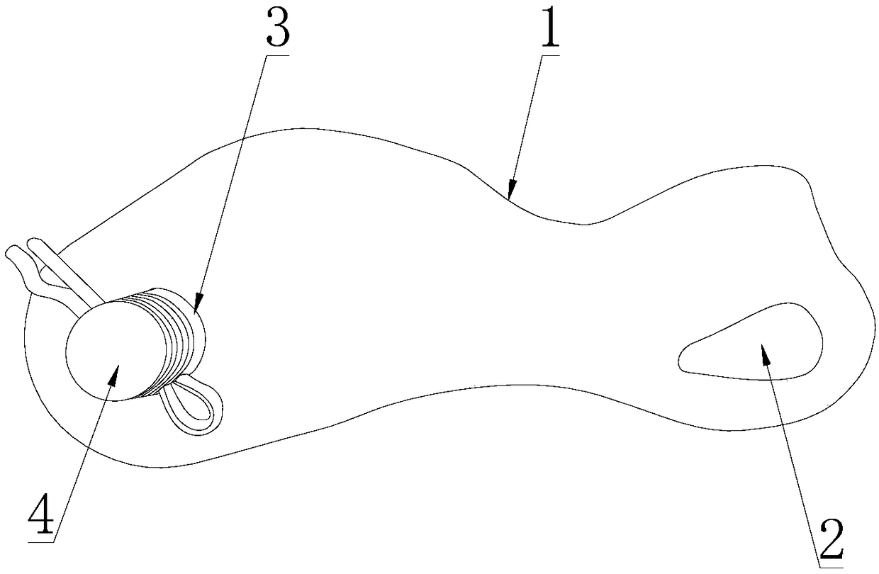
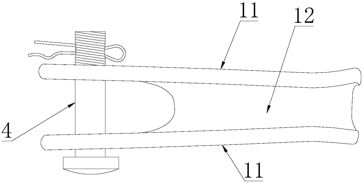
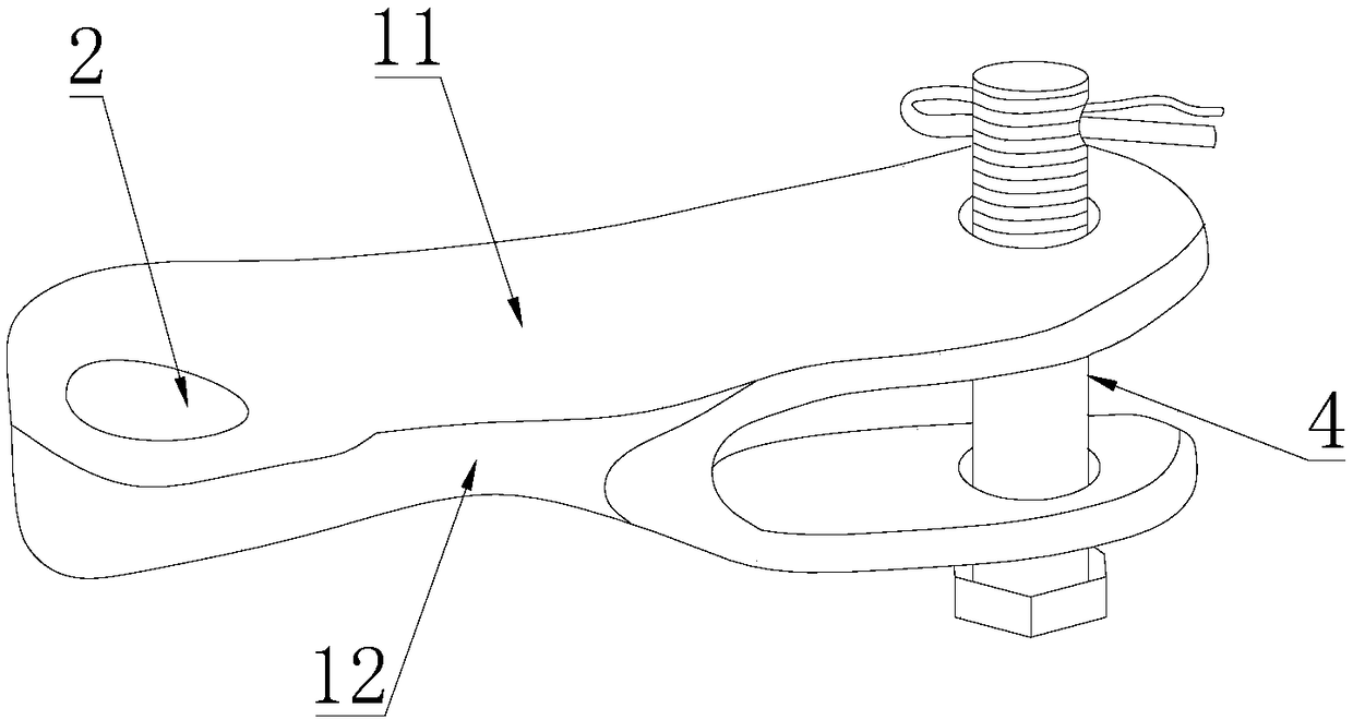
[0025] Such as Figure 1 to Figure 3 As shown, the present application provides a connecting piece for connecting the wire tensioner 6 and the wire rod 7, including a pin 4 and a trough-shaped body 1, the trough-shaped body 1 includes two side plates 11 arranged oppositely and connected to the The back plate 12 between the two side plates 11; at the first end of the grooved body 1, the two side plates 11 ...


PUM


Abstract

The invention relates to the technical field of engineering construction, in particular to a connecting piece for making a wire tightener connected with a stay wire rod. The connecting piece comprisesa pin and a groove-shaped body, and the groove-shaped body comprises two side plates which are oppositely arranged and a back plate which is connected between the two side plates; pin holes are formed in the portions, on the two side plates, at a first end of the groove-shaped body; gaps are reserved between the pin holes and the back plate, and the pin penetrates through the two pin holes; a connecting hole is formed in the portion, on the back plate, at a second end of the groove-shaped body; the connecting hole is formed in the side, opposite to the side plates, of the back plate. One endof the connecting piece is detachably connected with the stay wire rod through the pin, the other end of the connecting piece is connected with the wire tightener through the connecting hole, and thewire tightener and the stay wire rod are more convenient to connect and detach; by means of the extending function of the connecting piece, the wire tightener does not interfere with a UT wire clamp any more, and the wire tightening quality is not affected; the wire tightener is not affected, installation and detachment are convenient, and the construction efficiency is improved; a hook of the wire tightener is not directly connected with a bent ring so as to adapt to stay wire rods with different outer diameters.

Description

technical field [0001] The present application relates to the technical field of engineering construction, in particular to a connecting piece for connecting a wire tensioner and a wire rod. Background technique [0002] Guy wire production is one of the most common tasks in the construction of overhead lines. The existing technology is to connect the end of the steel strand to the UT clamp, and the UT clamp is connected to the bending ring of the guy rod on the ground to realize the protection of the steel strand. fixed. Before making the pull down handle, connect the hook head of the wire tensioner to the bent ring of the pull rod on the ground, tighten the steel strand, then tighten the UT clamp, remove the pull rod, and the operation is over. [0003] Due to the small opening of the hook head of the wire tensioner, the hook head cannot be connected with the bent ring of the pull rod for a pull rod with a large outer diameter, and it is necessary to use a wire rope to co...

Claims


Application Information

Patent Timeline
IPC IPC(8): E04H12/20F16G11/12
CPCE04H12/20F16G11/12
Inventor 刘京良罗志勇张国瑞赵语然
Owner 国网冀北电力有限公司管理培训中心
Why Eureka
Try Eureka