Drainage pipeline for measuring temperature, pressure and urine volume
A drainage tube and pressure measurement technology, which is applied in diagnostic recording/measurement, catheter, application, etc., can solve the problems of time-consuming, laborious, inconvenient operation, etc., and achieve the effect of high monitoring accuracy
- Summary
- Abstract
- Description
- Claims
- Application Information
AI Technical Summary
Problems solved by technology
Method used
Image
Examples
Embodiment 1
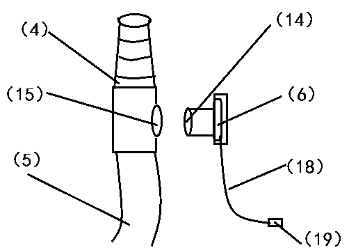
[0022] Embodiment 1: The preparation method in which the micro pressure sensor (6) of the present invention is arranged in the conversion joint (4).
[0023] 1. If image 3 As shown in the structure of the conversion joint (4), the injection mold for the conversion joint (4) should be prepared, and the right outer wall of the conversion joint (4) should leave a side hole (15 ).
[0024] 2. Using medical polypropylene material, the conversion joint (4) is produced by injection molding process.
[0025] 3. The serial port of the micro pressure sensor (6) uses a 30cm four-core wire (12) to communicate with the wire plug (13).
[0026] 4. Put the pressure measuring port (14) of the micro pressure sensor into the side hole (15) of the adapter, and seal the pressure measuring port (14) of the micro pressure sensor on the side hole (15) of the adapter with sealant. After drying the sealant naturally, use medical purified water to check the sealing performance. Under the pressure o...
Embodiment 2
[0027] Embodiment 2 The preparation method in which the pressure measuring port of the micro pressure sensor of the present invention is arranged in the branch interface of the pressure measuring chamber.
[0028] 1. If Figure 4 As shown, a four-lumen urinary catheter (1) is used, of which the left side is a fixed balloon cavity (22), and the middle catheterization cavity (21); the catheterization cavity (21) is located at the catheter branch interface (3) The fork is shaped as a pressure measuring cavity (20), and the catheterization cavity (21) communicates with the pressure measuring cavity (20); the right side is a temperature measuring cavity (23).
[0029] 2. Put the pressure measuring port (14) of the micro pressure sensor into the pressure measuring chamber (20), glue it with sealant, and check if there is no leakage.
[0030] 3. The pins of the micro pressure sensor (6) are welded to one end of the pressure measuring wire (18), and the other end of the pressure meas...
Embodiment 3
[0033] Embodiment 3 The present invention is matched with the monitoring equipment (11).
[0034] 1. If Figure 5 As shown, the fluid volume monitoring window (8) according to the present invention is inserted into the flow monitoring slot of the monitoring device (11).
[0035] 2. Use wires (12) to connect the temperature sensor (2), micro pressure sensor (6) to the signal acquisition board (9), and use wires (12) to connect the signal acquisition board (9) to the monitoring equipment (11).
[0036] 3. Turn on the power supply of the monitoring equipment (11) to dynamically and continuously monitor the patient’s body temperature and urine output; when it is necessary to monitor the patient’s bladder pressure, use the stop valve (7) to close the drainage line (5) to keep the bladder full of urine state, the bladder pressure can be measured.
PUM
 Abstract
Description
Claims
Application Information
 - R&D Engineer
- R&D Manager
- IP Professional
- Industry Leading Data Capabilities
- Powerful AI technology
- Patent DNA Extraction
Browse by: Latest US Patents, China's latest patents, Technical Efficacy Thesaurus, Application Domain, Technology Topic, Popular Technical Reports.
© 2024 PatSnap. All rights reserved.Legal|Privacy policy|Modern Slavery Act Transparency Statement|Sitemap|About US| Contact US: help@patsnap.com


