WYSIWYG mirror image shooting method, device and terminal

A photographing device and mirroring technology, which is applied in the photographing field, can solve the problems of high cost, long time to obtain a receipt for photographing, and high cost.

Active Publication Date: 2020-11-13
GUANGZHOU SHANGJING NETWORK TECH CO LTD
View PDF7 Cites 0 Cited by
  • Summary
  • Abstract
  • Description
  • Claims
  • Application Information

AI Technical Summary

Problems solved by technology

[0005] 1) High cost: Although the current self-service camera reduces manual assistance, it adds various equipment and instruments, which is expensive, and the cost of installation, transportation, and maintenance is high, which exceeds the affordability of ordinary consumer groups.
[0006] 2) Long time-consuming: The current self-service camera has many functions and many operating procedures, which is troublesome to operate, and it takes a long time for the masses to take photos and obtain receipts
[0007] 3) What you see is not what you get: Although the current photo self-service kiosks allow people to participate in the process of taking pictures and control the sovereignty to a certain extent, the preview effect seen by current technology is not the final or best effect. These self-service kiosks are located above the computer display or other positions close to the display screen, the eyes of individuals who see the real-time portrait in the display screen are not facing straight up, but have a deviation angle, either up or down, left or right; to make the eyes face up, the user must If you look directly at the camera, you will naturally not be able to view the portrait on the display screen, nor can you adjust your posture in real time; in the end, you have to let people take pictures and look at the camera. You cannot achieve "what you see is what you get", and look at the natural effect of taking pictures in the mirror

Method used


Image

  • WYSIWYG mirror image shooting method, device and terminal
  • WYSIWYG mirror image shooting method, device and terminal
  • WYSIWYG mirror image shooting method, device and terminal

Examples


Embodiment 1

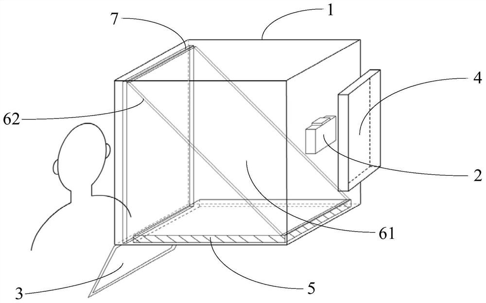
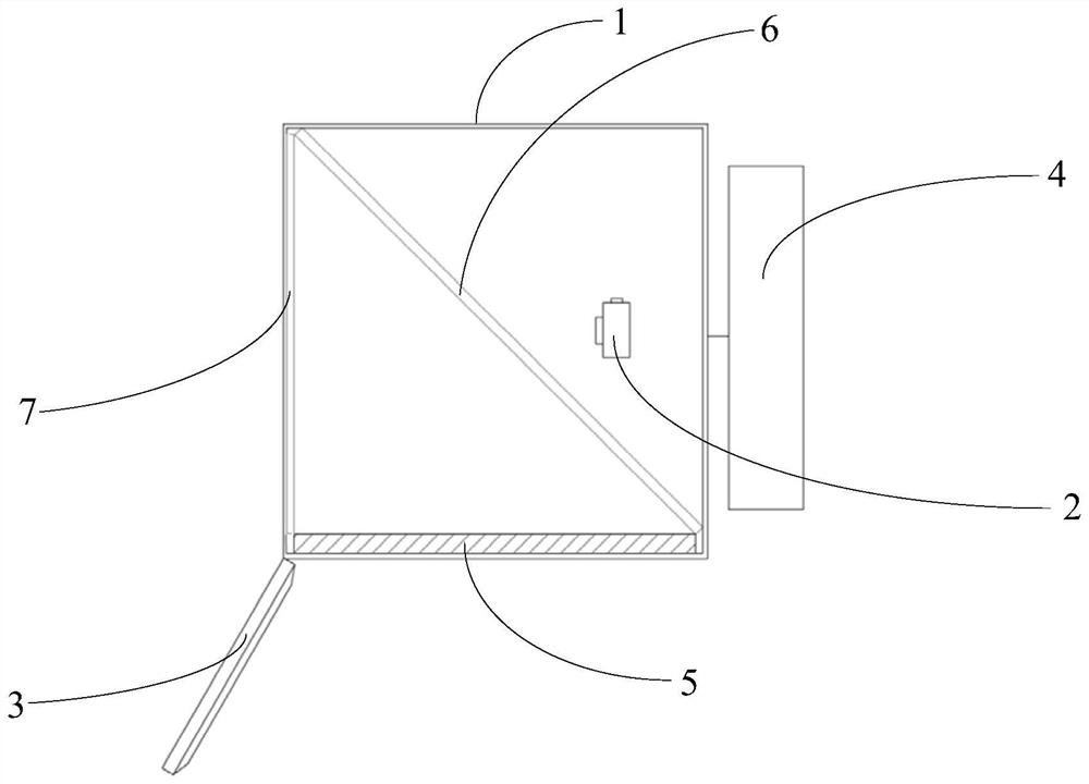
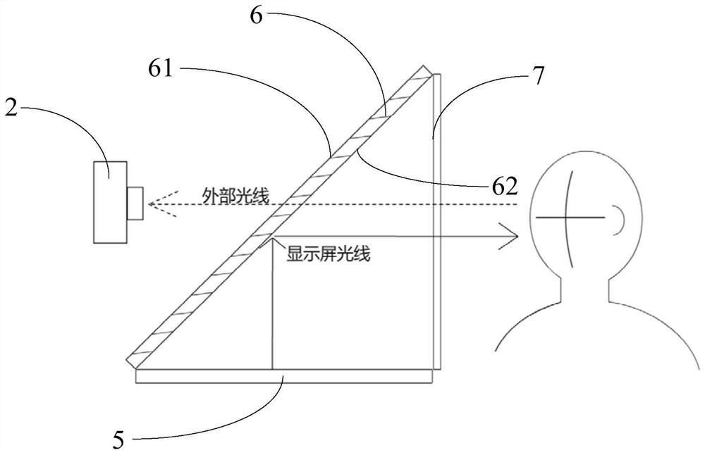
[0094] Such as figure 1 and figure 2 As shown, the present embodiment provides a WYSIWYG mirror image shooting device, which includes a frame body 1, a shooting device 2, an input device 3, a control device 4, a screen 5 and a one-way perspective mirror 6, and the frame body 1 It is a cuboid structure, which has a front, a rear, a top, a bottom, a left and a right, and the front is open, and the screen 5 is arranged at the bottom of the frame body 1, specifically arranged inside the bottom of the frame body 1, one-way perspective The mirror 6 is installed inside the frame body 1, which has a light-transmitting surface 61 and a reflective surface 62. The photographing device 2 is arranged inside the frame body 1 and is positioned behind the one-way perspective mirror 6. The control device 4 is transmitted through a data transmission line or other wireless The mode is respectively connected with the shooting device 2, the input device 3, and the screen 5.

[0095] The frame b...

Embodiment 2

[0113] Such as Figure 5 and Figure 6 As shown, the present embodiment provides a WYSIWYG mirror image shooting device, which includes a frame body 1, a shooting device 2, an input device 3, a control device 4, a screen 5, a one-way perspective mirror 6, a first moving mechanism (not shown in the figure) and the second mobile mechanism (not shown in the figure), frame body 1 is a cuboid structure, and it has front, rear, top, bottom, left and right, and front opening , the screen 5 is arranged on the top of the frame body 1, specifically on the inside of the top of the frame body 1, and the one-way perspective mirror 6 is installed inside the frame body 1, which has a light-transmitting surface 61 and a reflecting surface 62, and the shooting device 2 and the second The moving mechanism is arranged inside the frame body 1, and the shooting device 2 and the second moving mechanism are located behind the one-way perspective mirror 6, and the control device 4 is respectively co...

Embodiment 3

[0119] Such as Figure 8 and Figure 9 As shown, the present embodiment provides a WYSIWYG mirror image shooting device, which includes a frame body 1, a shooting device 2, an input device 3, a control device 4, a screen 5, a one-way perspective mirror 6, a first moving mechanism (not shown in the figure) and the second mobile mechanism (not shown in the figure), frame body 1 is a cuboid structure, and it has front, rear, top, bottom, left and right, and front opening , the screen 5 is arranged on the left part of the frame body 1, specifically on the inner side of the left part of the frame body 1, the one-way perspective mirror 6 is installed inside the frame body 1, and it has a light-transmitting surface 61 and a reflecting surface 62, and the shooting device 2 and The second moving mechanism is arranged inside the frame body 1, and the shooting device 2 and the second moving mechanism are all positioned at the rear of the one-way mirror 6, and the control device 4 is con...


PUM


Abstract

The invention discloses a WYSIWYG mirror image shooting method, device and terminal. The device includes a frame body, a shooting device, a control device, a screen and a one-way perspective mirror. The front part of the frame body is open, and the The control device is connected with the shooting device, and the screen is arranged on the top, bottom, left or right part of the frame body for displaying the output image of the control device, and the one-way perspective mirror and the shooting device are arranged inside the frame body. One end of the perspective mirror is close to or touches the screen, and forms a certain angle with the screen, and the other end is close to or touches the opening of the frame body, and the lens of the shooting device is directed toward the opening of the frame body through the one-way perspective mirror. The present invention can realize the screen mirror image reflected by the one-way perspective mirror for the user to face up to, and the portrait displayed in the screen mirror image is also the final photo effect obtained after shooting, and can realize the self-service shooting effect of what you see is what you get.

Description

technical field [0001] The invention relates to a shooting device, in particular to a WYSIWYG mirror image shooting method, device and terminal, belonging to the technical field of shooting. Background technique [0002] The traditional photo shooting method is to use a camera to assist a professional person to shoot, then export, process the photo, and finally display the result, because the person being photographed cannot control the process, and the quality of the photo depends on others or even luck, which is costly, time-consuming, and low in effectiveness. Poor, it is difficult to satisfy the masses. [0003] The self-service photo machines currently on the market, although reducing labor costs, assist the masses to take pictures independently and complete the collection of ID photos. The principle is that by setting a display near the camera, the computer processes and displays the image of the person captured by the camera synchronously. Individuals can adjust thei...

Claims


Application Information

Patent Timeline
Patent Type & Authority Patents(China)
IPC IPC(8): H04N5/232H04N9/31G03B17/12
CPCH04N9/3176G03B17/12H04N23/62H04N23/63
Inventor 郭毅俊李勇彬张雪婷
Owner GUANGZHOU SHANGJING NETWORK TECH CO LTD
Why Eureka
Try Eureka